
Jan
19
Having not posted for a while, and having recently paid my annual fees, it seemed appropriate to raise a glass to theDoctorsImages by posting some images of, well.., glassware. Items with high translucency and high reflectivity can be difficult to shoot cleanly, and there are various techniques with which to do this. Here I used a simple softbox to backlight or rimlight the subject, with either the white or black background, according to which look I wanted. The glasses rest on a black plexiglass sheet in all cases. The high-key images have black foam core reflectors on either side (just out of shot) and the low-key images have white foam core reflectors either side, again, just out of shot.
The images were taken using a Fujifilm XT-2 with a Nikkor 60mm Macro Lens and a single Nissin i60 (for Fujifilm) speedlight in an inexpensive Neewer Strip Softbox. Raw file editing was performed using Alienskin Exposure X4 with finishing and sharpening in Adobe Photoshop.
Gallery


Jun
03
Super-Resolution Imaging using a Fujifilm XT-20
Cameras / Computing / Fujifilm XT-20 / Photography / Super-Resolution Photography Posted by Robin
/
0 comments
Super-Resolution
Overview of Super-Resolution Techniques, What are we Discussing Here?
Super-resolution is a term with many modern meanings, but basically involves those techniques which add detail to poor resolution and grainy images. Fractal techniques for enlarging images have existed for many years, but are really just retaining existing detail, during enlargement, in a plausible way. More modern, single image, techniques however, can actually add extra detail that wasn’t there to begin with. Some techniques work by creating a dictionary of low resolution parts (for example in facial recognition) in which similar details are found (for instance an eye or a mouth) and patched together to form a complete picture. These new, but similar, parts are then substituted for higher resolution examples of the same details to create a higher resolution image overall. Whilst ingenious, this is a step removed from using the information within the image itself directly and not the subject of this discussion.
Another technique is known as resolution-stitching. In this technique a series of close-up images from a wider scene are taken and stitched together to make a higher-resolution whole. Taking the example of a landscape image, perhaps taken with a 24mm lens. The scene would be re-shot with a longer lens, say 100mm, in such a way that you have overlapping patches which can be stitched together using appropriate software. The longer the lens, the more detailed the final image will be. This is essentially the same as panorama photography and is also not the topic of this discussion. For the sake of completeness, when considering resolution stitching, there is a related technique attributed to the Wedding Photographer Ryan Brenizer called the Brenizer technique or sometimes the Bokeramah technique. This uses a telephoto lens, opened up to give a narrow depth of field, to take overlapping images to include the background such that the subject is very sharp but the background is blurred out, yet remains relatively wide angle. See Ryan in action via this B&H interview and video.
Finally, there are also artificial intelligence (AI) systems using a variety of neural networks and so-called deep learning which are also able to fill in missing detail in a range of images. One recent, well-known, example is Google’s RAISR (Rapid and Accurate Image Super Resolution) system as seen in this 2-minute papers video. For the interested reader there are a range of videos on neural networks in the YouTube Computerphile channel.
So what am I talking about? I’m talking about the super-resolution technique for photography popularised by Ian Norman from the photon collective in 2015. Take a look at Enhance! Superresolution Tutorial in Adobe Photoshop on YouTube and Ian’s excellent Peta Pixel piece A Practical Guide to Creating Superresolution Photos with Photoshop for more information on the technique and how it is applied.
Experiments with Super-Resolution
There’s little sense in me re-creating Ian’s work here, so I’ll move straight into my immediate reflections on reading his articles on super-resolution myself. I was away in Edinburgh for a long weekend and my immediate reaction was “I’ve got to try that!!” and “I wonder whether it will work with an X-Trans sensor camera” as I had my XT-20 with me. Only one way to find out, so I took a few random image bursts by way of experimentation.
Why the Worry About X-Trans?
I’ve read a great deal about the X-Trans sensor and am not sure what to make of the very partisan portrayals sometimes seen. From my own practical experience, I don’t find that the x-trans files are as easy to process when the shooting conditions have been difficult, and sharpening is often an issue unless you remember the tricks.
- Use Iridient X-Transformer to demosaic or..
- Turn off sharpening in Lightroom altogether, convert to a .tiff, then sharpen back in Lightroom or in Photoshop or..
- If sharpening in Lightroom has to be done, use the detail slider not the amount slider or..
- Use a different raw processor such as Capture One or On1 Photo Raw.
But actually, my concern was more about the green blocks of 4 pixels in the matrix. Would this effect the pixel averaging that takes place in the super-resolution process resulting in lower resolution than with a Bayer sensor? Would there be as much sub-pixel information available? This is the sort of situation where a little knowledge might be dangerous.
An Insight Into Sub-Pixel Imaging
I find it quite difficult to imagine how information can be gathered at a sub-pixel level when it is only captured at a pixel level. Looking into the research on image processing however, there are lots of different ways of extracting this information, even from a single image.
This paper by John Gavin and Christopher Jennison from 1997 called ‘A Subpixel Image Restoration Algorithm‘ gives a useful insight to the theory and practise. Indeed there are many applications in common usage including processing images of landscapes, remote sensing of active volcanos, locating and measuring blood vessel boundaries and diameters etc.
But will Ian’s process really reveal more detail, or simply smooth out the imperfections (noise) whilst placing the image on a larger canvas? Time for an experiment to find out whether super-resolution is a viable technique on X-Trans sensor cameras.
Technique
I used my Fujifilm XT-20 in manual shooting mode. The exposure was 1/250 second at an aperture of f8.0 for maximum sharpness. I used the highly respected ‘kit’ lens 18-55mm f2.8-4.0 set at 32.9mm. Several bursts of 25 images were taken, hand-held. For post processing I used Ian’s technique via specially constructed actions for 200% and 400% super-resolution. The original raw files were processed in Lightroom Clasic v7.3.1 using Auto settings, Camera ASTIA/Soft profile and the as shot auto white balance setting. Iridient X-Trans conversions were performed from within Lightroom. Final sharpening of the images was done via smart-sharpen with a setting of 300% at a radius of 2 pixels and no noise reduction. Detail shots were resized from the super-resolution images to 1200 by 800 pixels and saved via Lightroom’s export function as jpeg’s at 100% quality.
Image Results
Given the potential for artifacting in Lightroom, I generally demosaic special images in Iridient X-Transformer which, except for a single comparison just to see if there would be any difference, was the case here. So the Fuji raw files were demosaiced using X-Transformer prior to enlarging, aligning and then averaging using a smart object stack mode of mean. 5, 10, 15 and a full 25 images were enlarged to either 200 or 400%. Post enlargement, mild sharpening was applied using Smart Sharpen set at Amount 300, Radius 2 px and Noise Reduction 0%. Illustrative details from the scene are compared below. Representative details of the overall scene were selected and down-sampled to 1200 x 800 pixels for this section. This might not be the best way to demonstrate the improvements achieved by the super-resolution blending, but it does allow us to compare like with like.
Comparison results are set out as follows:
- Differences between Lightroom and Iridient X-Trans Demosaicing for the single image result.
- Differences between the 25 Image Blend at 200% size (96 mega-pixel equivalent) for Lightroom and Iridient X-Trans Demosaicing.
- 25 Image Blend at 400% (384 mega-pixel equivalent, Iridient X-Trans Demosaicing only).
- 200% and 400% with a 15 Image Blend.
- 200% and 400% with a 10 Image Blend.
- 200% and 400% with a 5 Image Blend.
- Please note that all blended shots are uncropped.
Single Image Results
Lightroom Demosaicing
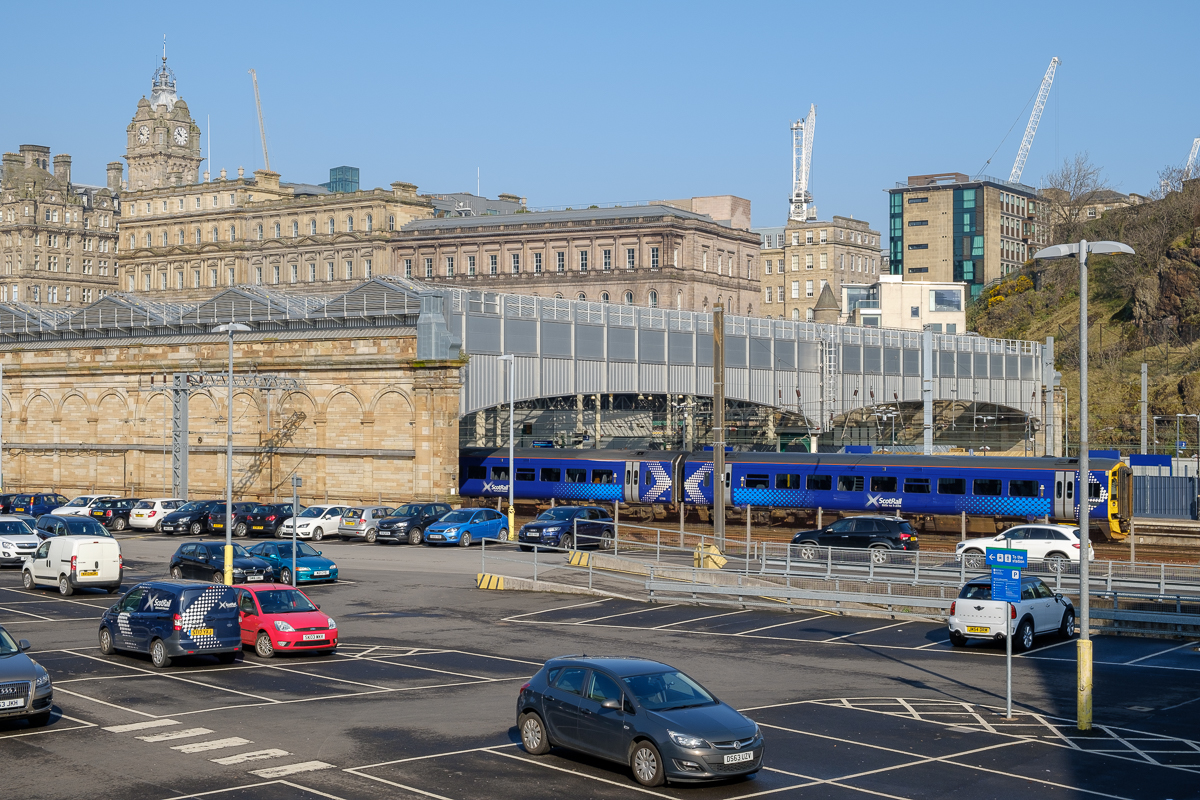
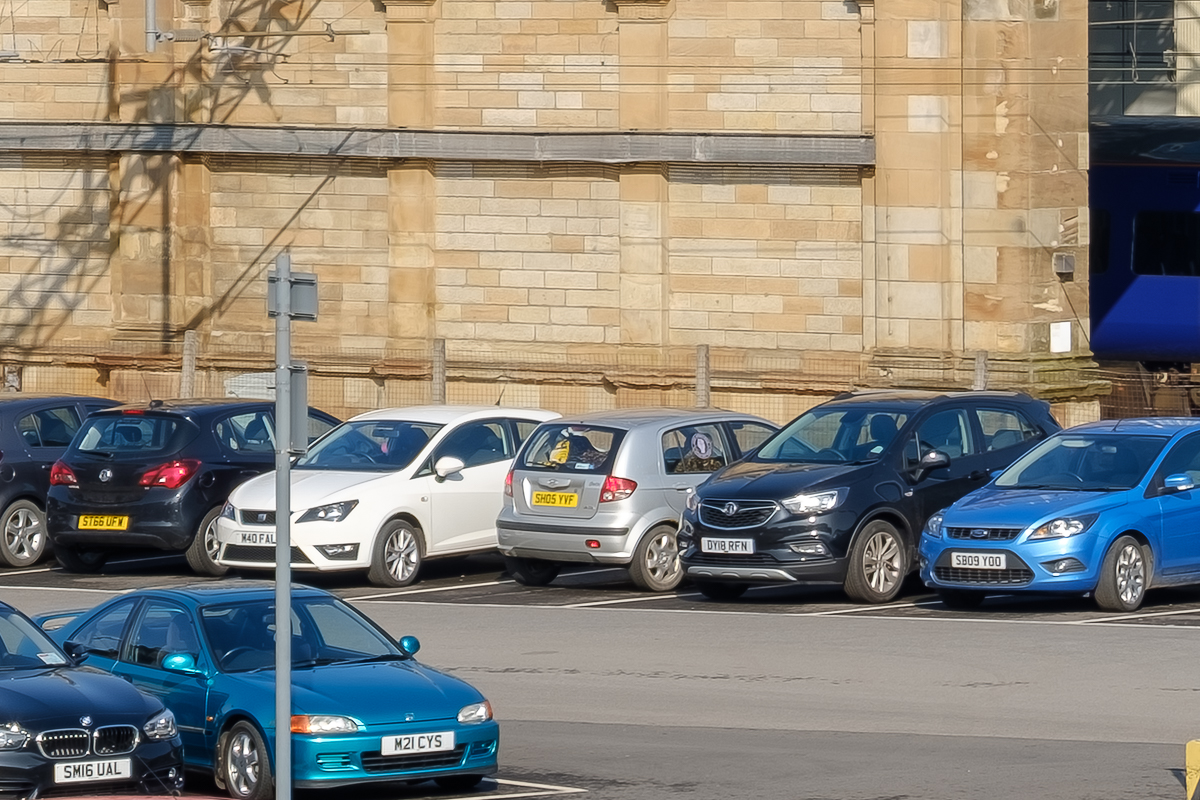
Waverley Station, Single Image..

Car Detail..
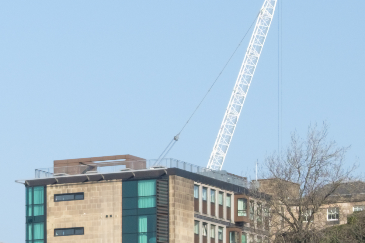
Crane Detail..

Clock Tower Detail..
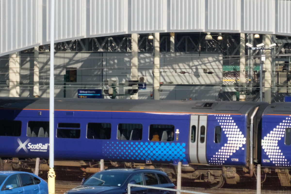
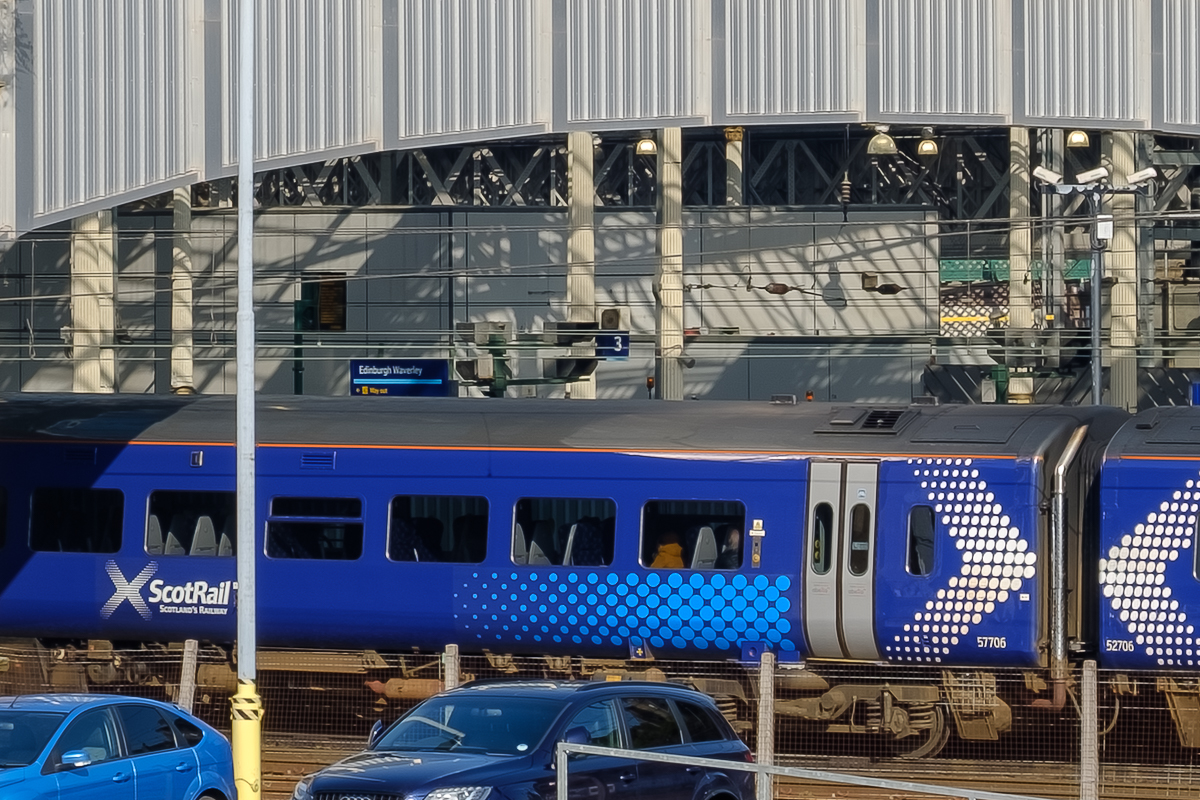
Train Detail..
Iridient X-Trans Demosaicing
Waverley Station, Single Image..
Car Detail..
Crane Detail..
Clock Tower Detail..
Train Detail..
25 Image Blend Results
200% Lightroom Demosaicing
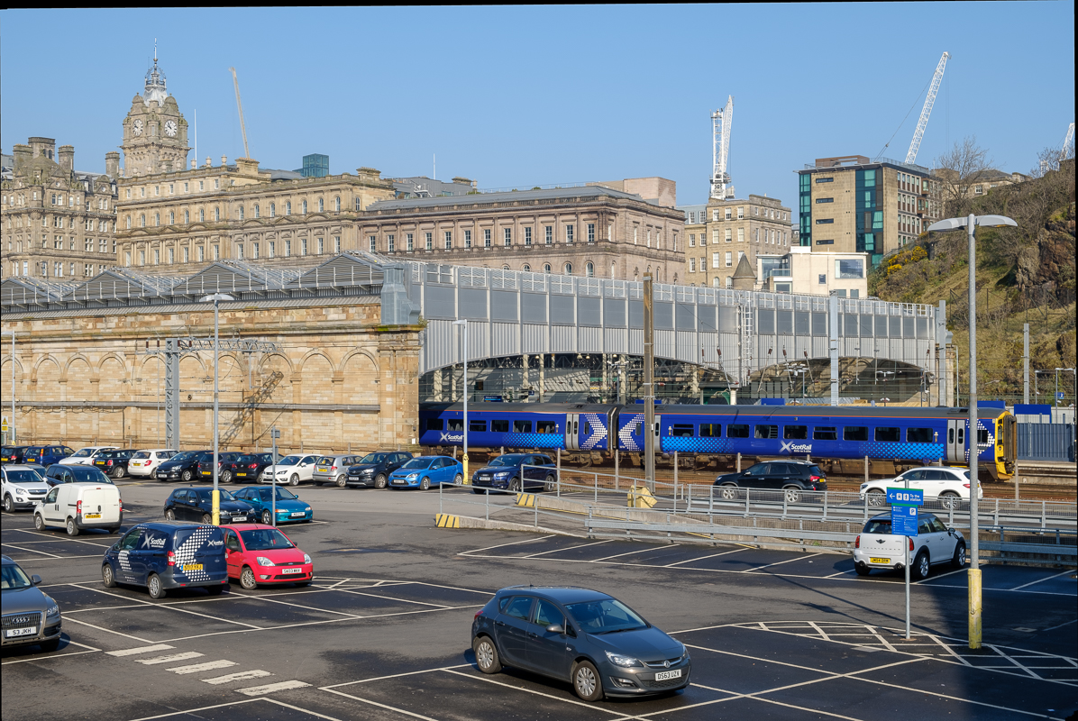
Waverley Station, Single Image..
Car Detail..

Crane Detail..

Clock Tower Detail..
Train Detail..
200% Iridient X-Trans Demosaicing
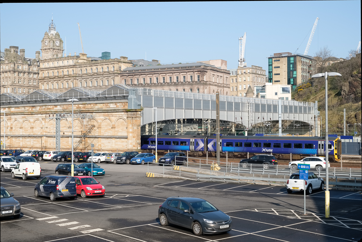
Waverley Station, Single Image..
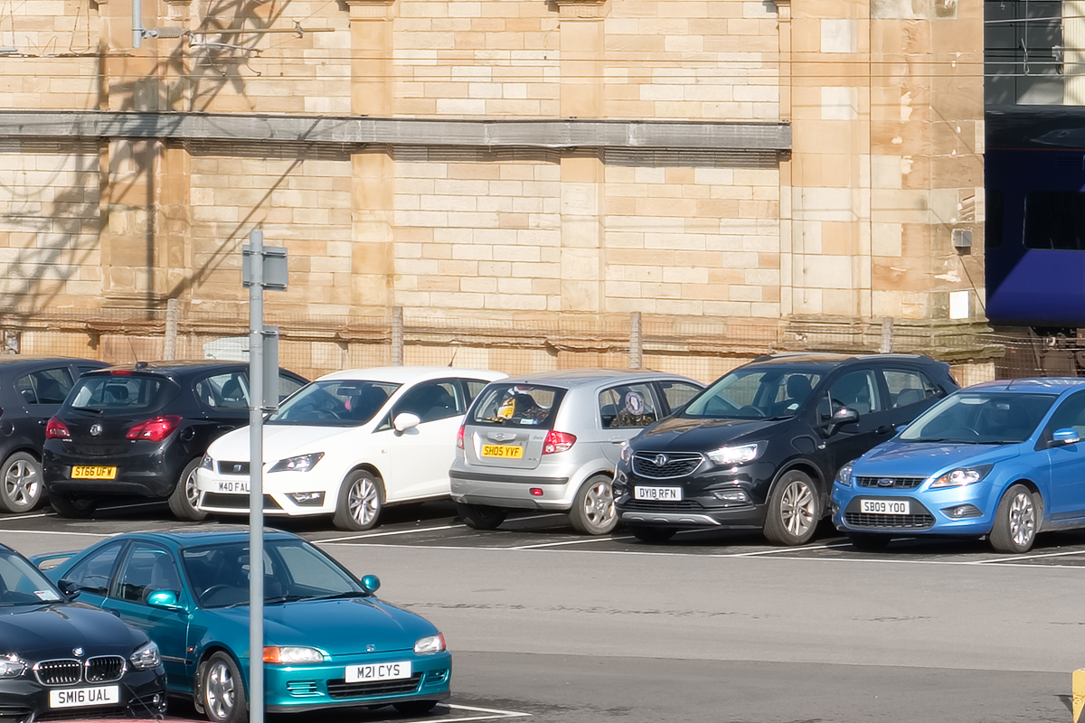
Car Detail..

Crane Detail..

Clock Tower Detail..

Train Detail..
400% Iridient X-Trans Demosaicing

Waverley Station, Single Image..

Car Detail..

Crane Detail..
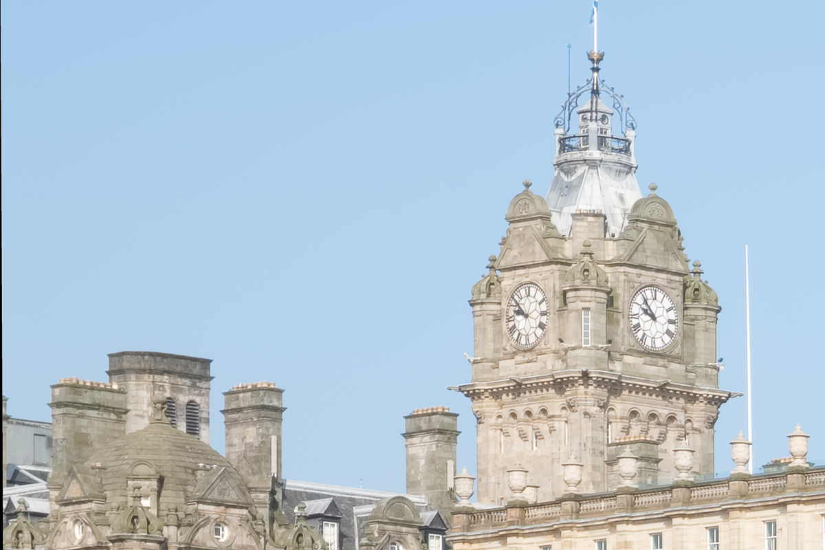
Clock Tower Detail..
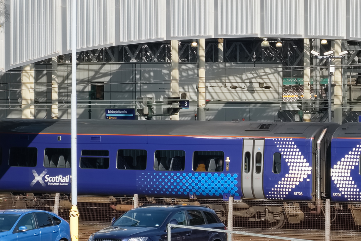
Train Detail..
15 Image Blend Results
200% Iridient X-Trans Demosaicing

Waverley Station, Single Image..

Car Detail..
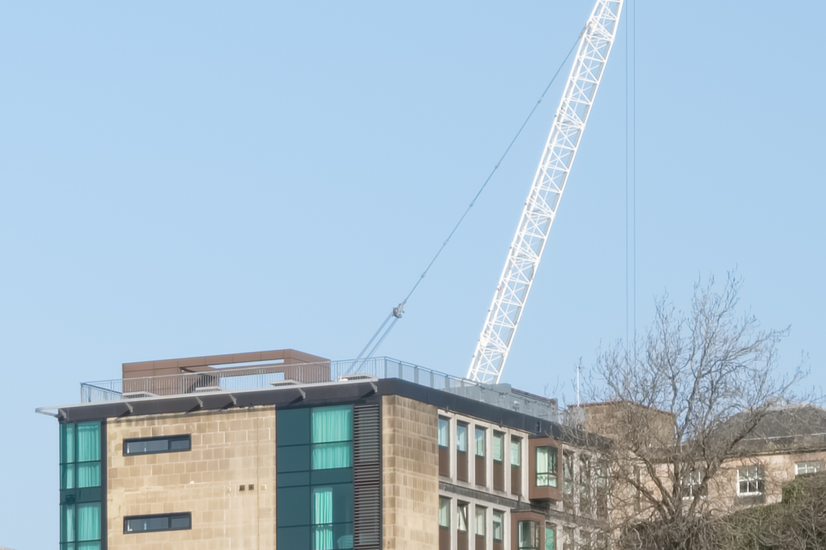
Crane Detail..

Clock Tower Detail..

Train Detail..
400% Iridient X-Trans Demosaicing

Waverley Station, Single Image..

Car Detail..
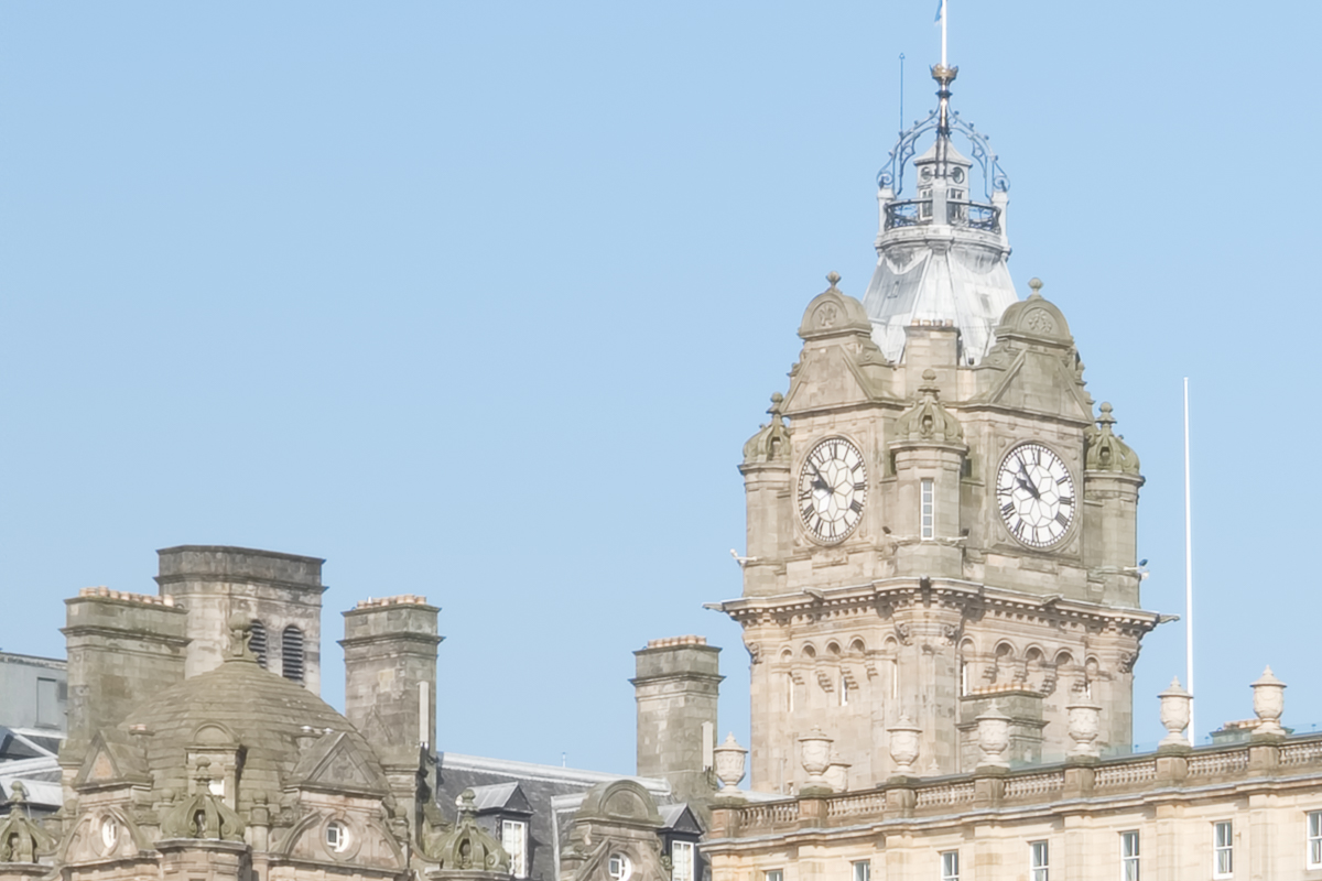
Clock Tower Detail..

Train Detail..
10 Image Blend Results
200% Iridient X-Trans Demosaicing

Waverley Station, Single Image..

Car Detail..

Crane Detail..

Clock Tower Detail..
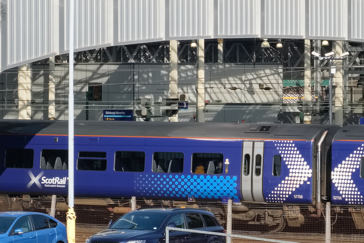
Train Detail..
400% Iridient X-Trans Demosiacing
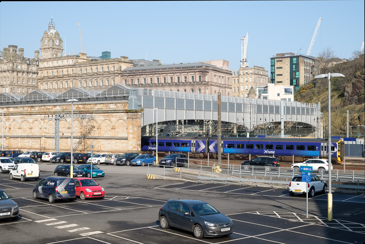
Waverley Station, Single Image..
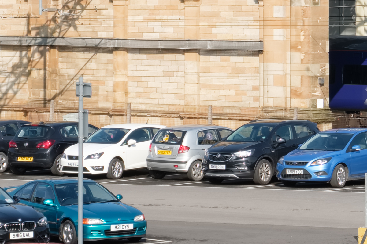
Car Detail..

Crane Detail..
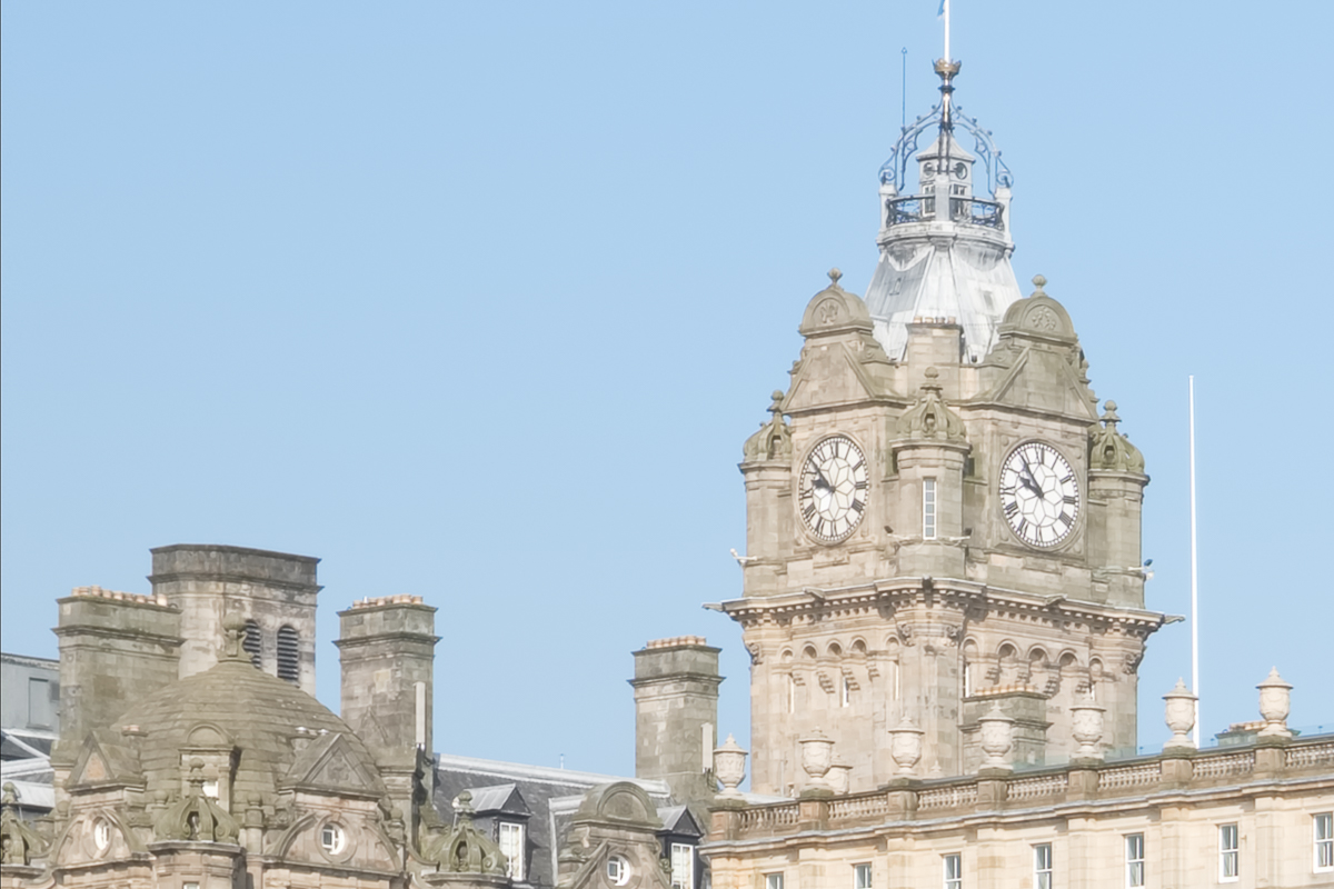
Clock Tower Detail..

Train Detail..
5 Image Blend Results
200% Iridient X-Trans Demosaicing

Waverley Station, Single Image..

Car Detail..

Crane Detail..
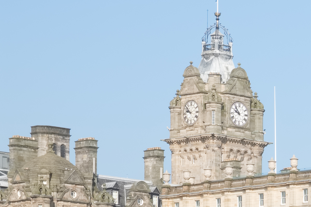
Clock Tower Detail..

Train Detail..
400% Iridient X-Trans Demosaicing
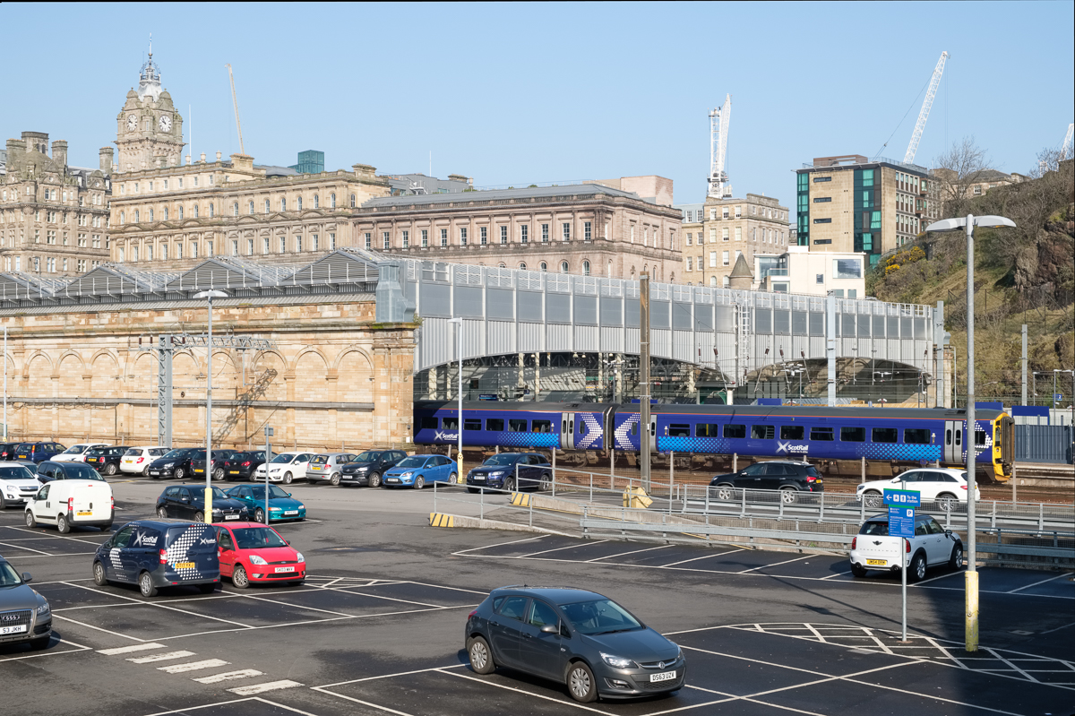
Waverley Station, Single Image..

Car Detail..

Crane Detail..

Clock Tower Detail..
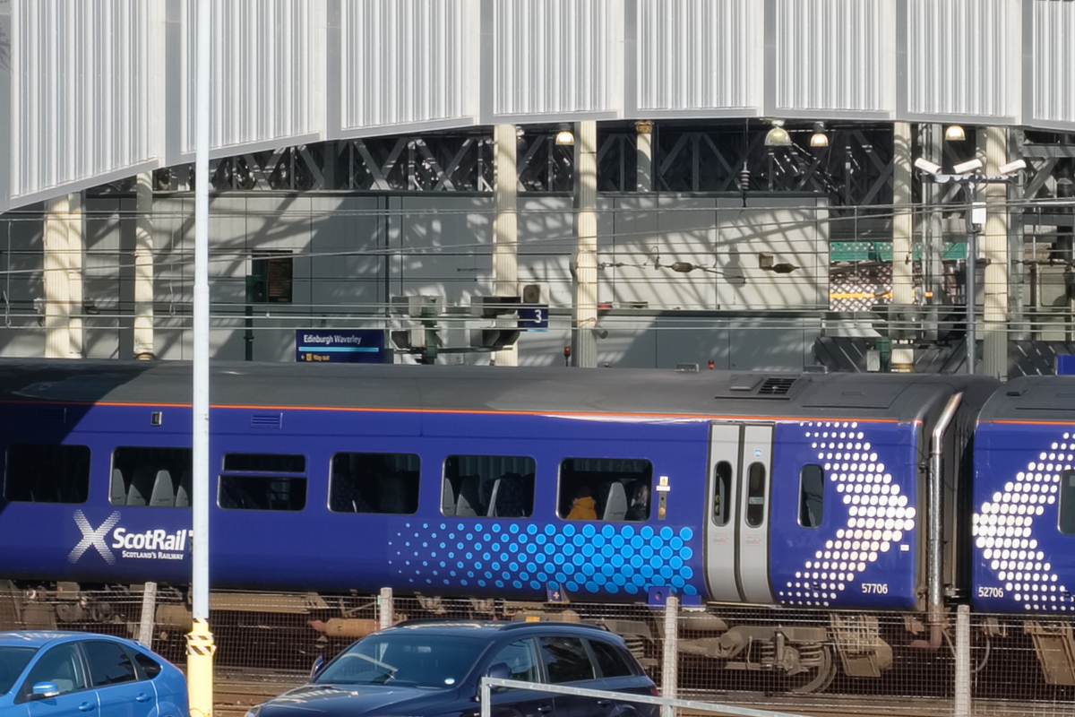
Train Detail..
Summary of Image Findings
Lightroom versus Iridient X-Trans Demosaicing in the Single Image Test
In this test, the first observation is that the Lightroom processing gave a darker result than the Iridient X-Trans did. Looking carefully at the individual images, the detail in the Iridient rendering is very slightly better with less aliasing and more pleasing colour in the overall image. Moving on to the single image detail shots, it is very clear that the Iridient Demosaicing is superior. There is a noticeable level of extra detail with the images looking sharper with an oveall sheen and sparkle missing from the lightroom images which look muddy in comparison.
25 Image Blends at 200%
In the overall Waverley image there was again a difference in colour between the lightroom and Iridient X-Trans renderings with the Iridient looking more pleasing with better contrast and slightly less harsh aliasing. There was less false colour though the detail was fairly similar to my eye.
Comparing the Lightroom single image to the Lightroom 25 image blend there is a very noticeable increase in the clarity of the image. The car detail images have a sparkle to them that was missing in the individual rendering and the extra details in the car number plates and the chain link fence behind the cars is remarkable. There was little noise in the original Fujifilm XT-20 raw files which were taken at an ISO of 200, but the 25x image blends are totally noise free.
Comparing the Lightroom blend to the Iridient blend, there are further gains in image resolution and quality, to me most noticeable in the appearance of the chain fence where it overlaps the train wheels in the train detail image. The similarity of the colour of the rusty chain link to the false colour shadows under the train in the Lightroom image makes the link much more difficult to see in the Lightroom image.
25 Image Blends at 400%
I think that the key question here is whether there is any extra detail at all in a 400% size image compared to the 200% images. Here we are comparing simply between Iridient X-Trans demosaiced image blends only as I did not perform the 400% blends using a Lightroom render for reasons of time (more on the time aspect later).
To my eye, the 400% results were softer with less contrast, but noticeably less aliased and artefacts were fewer around small details like the number plates in the car detail image. It looked as though the 400% images might respond really well to a mid-tone contrast boost which may reveal this extra detail more clearly. The 400% 25 image blend took six and a half hours to render (after many failures to complete and certain tweaks being necessary to my computer hardware). As such the small gains may not be worthwhile as a routine workflow.
Reducing the Number of Blended Images
Reducing the number of images from the 20s to the teens may improve the speed of processing considerably, but is the lost quality acceptable. How many images do you really need. Ian Norman likes to use about 20 images which clearly works well, so I have started from 15 images working down in 5s.
Looking particularly at the Car Detail shots at 200%, there is an improvement in detail above that of a single shot even with 5 images. The improvements in detail and contrast improve incrementally the more images you add. 15 images is quite acceptable, though 25 gives a surprising amount of extra contrast and detail.
Going through the same exercise with the 400% images there is much less difference in contrast and detail as you increase the number of blended images. At 400% even 5 blended images gives a substantial increase in detail over the single image, so given the time in processing there may be little advantage in going to much larger frame numbers.
Practical Difficulties with Super-Resolution
With a 24 mega-pixel camera sensor, at 200%, you are essentially creating a 96 mega-pixel image (12,000 x 8,000 pixels). With a 400% super-resolution image you are creating a 384 mega-pixel image (24,000 x 16,000 pixels). Each 24 megapixel layer in your super-resolution stack will be 137 megabytes in size at 100%, so for a 25 image stack that’s 25*137 megabytes. Increase to 200% size and this becomes 25*549 megabytes file size or at 400% size a massive 25*2.15 gigabytes.
Needless to say that these file sizes are problematic for Photoshop to work with. It can do it, but it needs a massive amount of memory to do so. Way more memory than an average domestic PC will have.
Out of Memory?
I have a decent specification PC even though it is now a few years old (see link). But I was unable to process 400% super-resolution images with 25 layers because I kept getting out of memory messages half way through. It took a while to work out precisely which memory was running out, but it turned out to be both the Photoshop scratch disk and the Windows page file.
Of Scratch Disks and Page Files..
My PC uses a 500 GB M.2 SSD for the operating system and programs and, by default, Windows uses the operating system drive for its virtual memory management. Photoshop also uses the operating system drive for its scratch disc. Basically, my C: drive was filling up with virtual memory files and grinding to a halt. As good fortune would have it, I have a second, empty, high speed M.2 drive in my system so I was able to relocate both the Windows page file and my Photoshop scratch disc to that 500 GB drive. Sadly that still wasn’t enough space for these gigantic files and I had to add slower hard-drive capacity to the Photoshop scratch disc list after which all was well. Nevertheless, having had to wait six and a half hours for photoshop to finish, I only ran one 400%, 25 layer, file through the process. This is definitely a major limiting factor.
Is Super-Resolution Worth Doing?
My analysis is that it is worthwhile for some types of imagery:
- When you are in a push, especially in situations requiring high ISO to reduce noise as well as improve detail.
- For architecture and some indoor shots.
- For landscape photography in calm weather.
- In situations where you might want to make a very large print.
- When you don’t have a high resolution camera available, or where resolution stitching is not viable because you don’t have a long lens handy.
- In situations where extreme upscaling is necessary (400%) the availability of 5 images or more for this process gives a significant lift to the detail of the image.
Nevertheless there are situations in which you couldn’t use the technique, for instance where there was a lot of movement in the scene, or where every image is substantially different. Notwithstanding this some authors have used long-exposures for blurring water with this technique, so in some circumstances movement per se may not be an absolute barrier. It may also be used where small changes in perspective mean that the images can still be aligned (although there will be more waste within the image).
Final Thoughts
Iridient X-Transformer does not respect the Lightroom processing settings, but does use the in-camera film simulation. I would have been better off not making any development changes in Lightroom to ensure that judgements of the differences in resolution and contrast were not colored by them.
Feb
15
Uni-White Balance on a D850
How Much Difference Does it Make to Assessing ETTR?
I’m very much in favour of using an ETTR (expose to the right) methodology with all my RAW shooting. Uni-white balance is a way of improving the exposure information from your on-camera histogram, which is based on the jpeg processing currently in force when you take your shot. This jpeg processing, in turn, is determined by the picture control that you have selected in-camera. Setting a neutral picture control, with flat contrast and zero sharpening, is itself a way to improve the accuracy of the in-camera histogram, because it limits extra white point and black point clipping. Unfortunately this only takes you so far. A larger difference can be made by using, so called, uni-white balance. But how much difference does this make in practise, and crucially, is it useable?
What is Uni-White Balance?
Background
Checking the histogram and the clipping information is part of everyday routine for many photographers. Sadly the histogram and clipping information (blinkies) do not closely relate to the information captured in a RAW file. This is because the histogram is taken from a version of the JPEG file that the camera produces (stored inside the RAW file). The correlation between the information in the JPEG file and the RAW file depends upon the modifications that occur during the processes of:
- White Balance
- Application of a Contrast Curve
- Colour Profile Conversion (sRGB, Adobe RGB)
- Gamma Correction
- User Chosen Picture Controls or Settings (Contrast, Saturation, Sharpening etc)
These changes frequently lead to a pessimistic assessment of what the RAW file actually contains, leading to apparently blown out highlights for channels that are not really fully saturated in the RAW data.
In Camera Histograms
It’s difficult to know, for certain, exactly how the in-camera histogram (prior to the shot being taken) is really calculated. What may be happening is that the histogram that you see is derived from only a part of the image processing chain that produces the JPEG file. In live view it is likely that the camera sub-samples (to make the calculation faster) and assigns the pixels to buckets. To make the JPEG, the camera performs the additional 8×8 discrete cosine transform, file compression and formats the data in the nominated pattern for a JPEG file format. The histogram that you look at when viewing the file, post capture, is probably calculated from the JPEG preview file embedded within the raw file itself.
Almost always, the in-camera histogram, after this extensive processing, will not help you perform ETTR as it will show clipping at the right side of the image well before the raw data is actually clipped. Choosing the widest gamut camera color space (Adobe RGB usually) available, setting uni-wb and using the lowest contrast setting available (including removing any sharpening) will all help to give a closer approximation.
The RAW Image
The sensor in a Nikon D850 is covered with a so called colour filter array using a Bayer Pattern. Sometimes referred to as an RGBG pattern, the Bayer filter mosaic was invented by Bryce Bayer whilst working for Eastman Kodak in 1976. Colour filters are needed because the typical photo sensors detect light intensity with little or no wavelength specificity, effectively only measuring luminosity rather than colour.
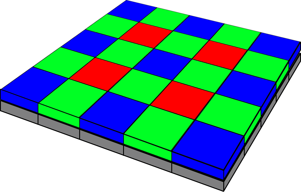
Bayer Array
With a colour filter array in place, a calculation can be performed for each pixel to work out its precise colour based on its own colour and intensity, alongside those surrounding it. This is called demosaicing. The Bayer pattern has twice as many green filters as red and blue. The colour filter’s spectral transmission, and density, will vary between manufacturers and need to be taken into specific account during the demosaicing process and translation into an absolute colour space.
The extra green filters provide more luminance information, which mimics the way that the human eye fabricates the sharpest possible overall colour image. In other words the human eye sees luminance and grayscale better than it does colour, and luminance better in the greens.
Demosaicing
Demosaicing is the process of turning the raw sensor information into an RGB colour map of the image. Various algorithms exist for this process though, in general, slight blurring takes place as a result of the demosaicing process. Some algorithms try to take edge detail more into account in order to mitigate the overall colour averaging process that takes place over groups of pixels. In order to calculate the red, green and blue values of each pixel (i.e. the missing two thirds as only the red or green or blue value is measured for the index pixel according to it’s colour filter), the immediate neighbour non-index colours surrounding that pixel can be averaged. Thus, in some sense, the colour map is two thirds fabricated and only one third measured!
Conversion to a Standard Colour Space
The raw data is not in a standard colour space, but can be converted to one later. As such, it does not matter what you set your camera to (Adobe RGB or sRGB) because the raw data is preserved with the colour space setting representing merely a label. The details of conversion from raw data to a standard colour space contain many complications. For a start a camera sensor is not a colorimeter so it is not measuring absolute colours anyway. You may hear this stated as camera sensors ‘not satisfying the Luther-Ives or the ‘Luther-Maxwell condition’. Secondly, human eyes and colour filter arrays see different spectral frequencies which can lead to camera metamerism. Camera metamerism is a term that covers the situation in which there is a discrepancy between the way a camera and a human sees colour. Typically colours that the camera sees as the same, which a human sees as different, or vice versa. Metamerism also occurs in printed output, especially with pigment inks. Jim Kasson’s excellent article on how cameras and people see color is a useful read for more information, as is John Sadowsky’s article on RAW Files, Sensor Native Color Space and In-Camera Processing.
White Balancing and the Green Coefficient
The next step of in-camera image processing is to apply the white balance. There are lots of ways to do this involving matrices and RGB coefficients. In this scheme the Green coefficient is set at 1 and the Red and Blue coefficients define the neutral axis of the image.
Final Steps in Camera Raw Image Processing
Finally, there will be the addition of a gamma correction to each of the 3 colour channels. In essence this correction takes account of the non-linearity of the human perception of tones and can also increase the efficiency with which we store colour information.
Uni-White Balance
The ‘uni’ in Uni-White Balance really refers to 1. That’s 1 as in a white balance in which the red, green and blue coefficients are all set to the same value (i.e. 1).
When a camera or post-processing software (RAW convertors) apply a white balance to the RAW data, they generally leave the green data as is and apply a factor (the coefficient) to the red and the blue channels. So, for example, at sunrise and sunset when you have an abundance of warm (red) light, the red is lowered and the blue increased.
On a cold overcast day, or in shade, the reverse occurs so that the red is increased and the blue lessened. This factor, or coefficient, is thus a divider or a multiplier of the actual raw data from the sensor for the red and blue pixels. This may therefore lead to either an underestimate or overestimate of how much red or blue channel saturation is really present. In other words the red and blue channels can look either under or overexposed erroneously compared with the actual values recorded in the raw data from each red and blue photosite.
Uni-White balance uses coefficients of 1 for red, green and blue which thus leads to accurate histograms and highlights for your raw data provided that any picture control (for Nikon) in force does not artificially boost saturation or contrast in one or more channels.
More on White Balance
As mentioned above, the white balance is the linear scaling of the RGB channels of the RAW file. This means that the levels of red and blue are typically multiplied by a factor greater than 1 which scales them to compensate for the different sensitivities of the filtered photosites, and also the colour of the light in the scene (eg. daylight, tungsten or shade). These linear factors can be as high as 2 or even 2.5 leading to an apparent increase in exposure for the channel being scaled from 1 EV to 1.3 EV. Similarly, decreases in exposure may also occur leading to desaturation of the image in some colours.
Setting up a Nikon D850
There are techniques that approximate to Uni-White Balance and techniques that are specific to a particular camera. Both are comprehensively covered in Jim Kasson’s ‘the last word‘.
Approximations to Uni-White Balance
The shortcuts to Uni-White Balance do not work on all cameras.
Balance to Maximum or Minimum Saturated Pixels
Taking a dark frame image (for instance with the lens cap on), or a completely overexposed and blown out image, as a reference for White Balance is one way to get the same information in all the channels. This will sometimes work for some Canon cameras, but doesn’t work for Nikons. To check whether you have achieved the desired white balance check the red and blue white balance coefficients in the camera’s EXIF data. They should be within five or ten percent of one.
Manual White Balance Technique
In this method you set the white balance to 3800k (or as close as you can) and then set the colour bias (or tint) to as green as it will go. Take test exposures and check the EXIF white balance coefficients as above. Use the manual white balance to tweak the settings but beware that many cameras just don’t have enough adjustment range to get you to a full Uni-White Balance.
Use a Uni-White Balance File Prepared for your Camera by Someone Else
In this method you copy the white balance setting from a copy of an image taken by another camera, of the same make and model, with Uni-White Balance already set up. Copy the image to a memory card (with a suitable name and in a suitable folder so that the camera can find it) and tell the camera to use the white balance coefficients from the image as a white balance preset.
Avoid Uni-White Balance and ETTR Using Another Method
If you are confident that you know what the brightest part of your capture will be, you can meter for that, apply +3 stops of exposure compensation, and not use the histogram at all.
Setting up a Specific Camera for Uni-White Balance
I have personally used the method described by Jim Kasson on his blog. Since you are also free to use this resource I will not précis it here, suffice to provide the link and make a few comments on issues that I found particularly challenging. In essence, the task consists of taking defocussed, fully saturated, pictures of red, green and blue on a fully warmed and calibrated monitor using (for instance) photoshop. A second program (I used Rawdigger) gives you the average pixel values of the Red, Green and Blue in the raw images so that these values can be entered into a spreadsheet that Jim provides. The spreadsheet gives you values for a corrective (magenta) colour which you create and display on your monitor. This colour is then used to white balance your camera and store a preset for future use.
As I traversed Jim’s excellent protocol, the only real question that I had was about whether to use exactly the same exposure for the White Balance as for the RGB target images. It turns out that it doesn’t really matter. It doesn’t really matter what the exact exposure of the RGB targets is either, you really can let the camera decide. Secondly, when it comes to entering the desired camera values in the spreadsheet, it does make a difference to the magenta target brightness values calculated (but not the hue) so again they are not critical. Finally, I calibrated 5 cameras in one session and found that it is quite easy to forget to enter the desired camera values. So keep an eye on that detail.
Side Effects
It goes without saying that success in this process leads to raw images with a heavy green cast (the background of this image was neutral gray). This is easily dispensed with by choosing an appropriate white balance preset in your image processor of choice, during post. After a while you stop noticing the cast and I tend to leave Uni-White Balance set most of the time.
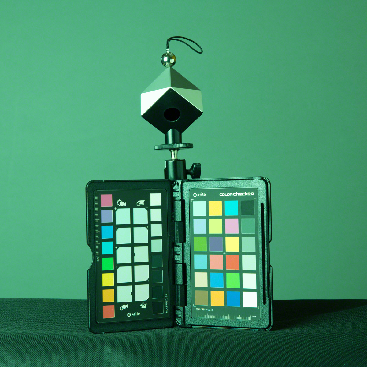
Image with Uni-White Balance Applied
Picture Control Settings
As mentioned previously I used the NL picture control preset but edited it to remove all sharpening. I left contrast at zero, though you could make it lower still. Just as an aside, Nikon makes the excellent Picture Control Utility 2 which comes free with other Nikon software or can be downloaded from the link included. This utility allows you to organise and manage your picture control presets so that they may be distributed between Nikon cameras. There are some features within the utility that are not available for adjustment in the camera picture control menus.
Testing the Effects
The Setup
My goal with this testing was simply to get a feel for how the histogram looks between shots taken with, in this case Auto White Balance, and Uni-White Balance across a range of exposures. To maximize accuracy I chose to use a manual flash exposure in order that there was no chance of the light levels changing between shots. I chose an exposure that meant the flash was the major lighting for the scene and no chance of the ambient lighting causing specular highlights. All shots were taken at 1/160th second at f11 and an ISO of 800. There is a debate to be had about which ISO to choose, but given that the D850 has an ISO invariant sensor, and that I’m often shooting wildlife in low light conditions, this seemed a reasonable compromise for this experiment.

Lighting Setup with Targets
As can be seen from the image at left, the target was an X-Rite Color Checker Passport beneath a Datacolor SpyderCube White Balance target. The advantage of the SpyderCube is that the metal ball atop creates clear specular highlights, and the dark face has a light trap within it to give a definite black point.
The colour in the scene comes from the Color Checker only, with everything else being neutral. You can see a small colour cast across the grey background in the production shot, but this is removed by the ambient under-exposure and flash illumination. There did remain a small luminosity gradient across the background however as a result of using only one softbox. This is partly mitigated by the V-Flat reflector and, not a significant confounding variable in this test. The camera was tripod mounted and did not move during the test shoot.
Testing Procedure
Below is an image of the ambient light at 1/160th second, f11 and ISO 800. The test itself consisted of making 10 exposures at 1/3rd stop intervals via a Nikon SB910 Speedlight set to manual exposure. The range was 1/8th power to 1/64th, chosen to be well within the normal range of the speedlight output (Full power to 1/128th). Shooting at a maximum of 1/8 power also provides insurance against the flash not being ready for the next shot. The flash was triggered using a Pocket Wizard Flex tt5 with a mini tt1 on camera alsongside the AC3 controller for easy and precise flash settings.

Ambient Exposure
The Nikon D850 was set to Raw shooting and a set of 10 shots using Auto-WB 1 were made (Light to Dark exposures) followed by 10 shots using the Uni-White Balance Preset (as above). Again, bright to dark exposures.
The 20 Raw Files were then inspected on the back of the camera and the histograms photographed. The Raw Files were brought into RawDigger and examined for highlight clipping in each exposure. These values were entered into a spreadsheet (see below).
Results
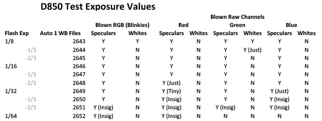
Auto-1 White Balance Data
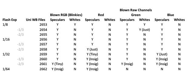
Uni-White Balance Data
The first thing to notice is that these tables are, barring one small detail (a tribute to Nikon flash consistency) exactly the same. In other words (and reassuringly) the exposure captured was not materially altered by the application of Uni-White balance.
Does this mean that the back of camera histograms are the same? Not at all! My first examination was to look at whole stop increments.
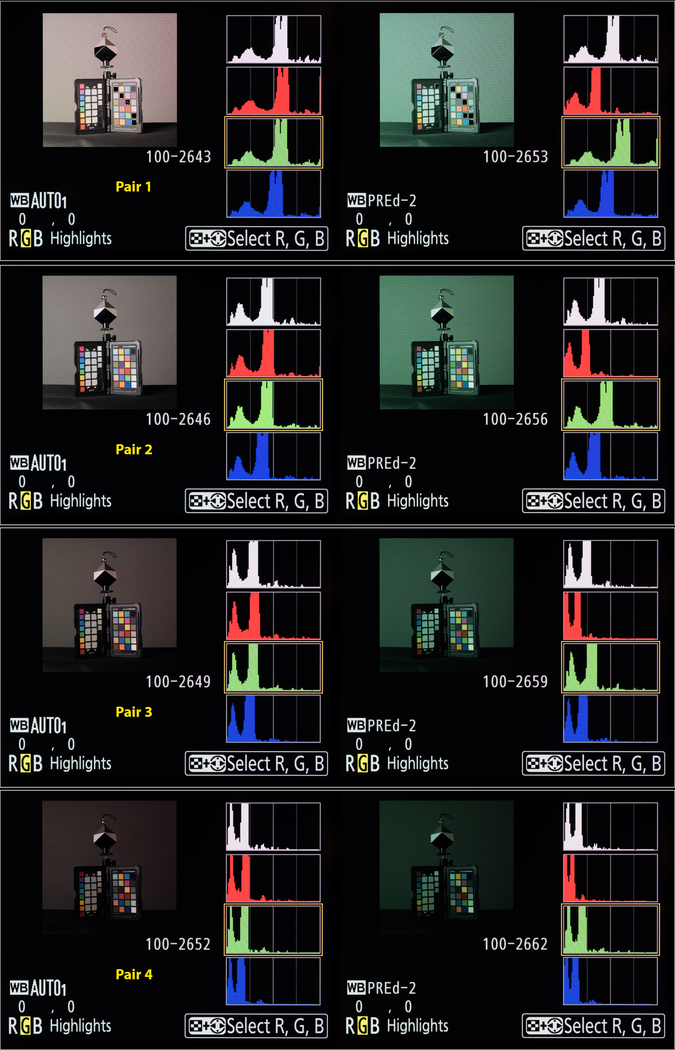
Composite Histogram Analysis
You can compare the histogram results to the RawDigger results by looking at the Hist No in the spreadsheet above (I.e. the number out of 208 in the images below).
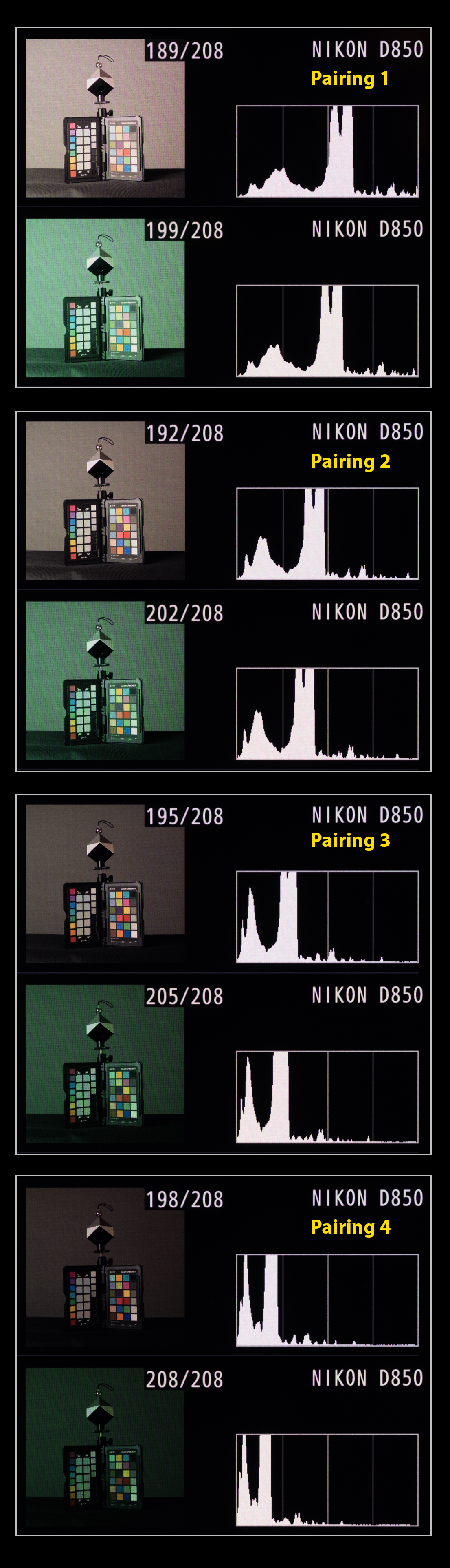
The graphic shows four images, one stop apart in auto and uni WB pairs. As you can see the Uni-WB composite histogram is consistently left shifted (demonstrating more exposure headroom) in the Uni-White Balance partner. It’s reasonably easy to compare the peaks between histograms. The horizontal movement of peaks between successive Auto-1 White Balance Composite Histograms gives a measure for a one-stop difference in exposure. Bringing the images into Photoshop and applying the measurement tool, it looks as though a stop measures about 228 units, on average. This being the distance between the same histogram peak between images, on a full sized image. Comparing this between successive Auto-1 White Balance / Uni-White Balance pairs shows a distance of 88 units on average and this represents a 0.39 Stop improvement in accuracy on the composite histogram.
RGB Histogram Analysis
The image below shows 4 RGB histogram pairs with each pair representing 1 stop exposure difference, decreasing down the page as with the composite histograms above. At first the picture seems very confusing. The inflated green channel (or perhaps I should say, the more representative green channel) looks at first as though it may be a problem. Looking at the RawDigger white clipping values for the Green channel though, as with the images of the on camera histograms below, you can see that this reduces at the same rate in both sets of files and looks worse than it is. Also, because the red and blue channels are also shifted, you still end up with a better composite histogram. For this reason, ease of interpretation may improve by just using the composite histogram whilst Uni-White balance is in place.
RGB Histogram Pairs, 1 Stop Apart
Usability In Practise
I am still gaining experience with this technique, though my initial impressions are good. I was worried that the heavy green cast would put me off using Uni-White Balance, though in practice this is not the problem I first thought. You stop noticing it after a while. I was also concerned about moving back and forth between the white balance presets, but on the Nikon D850 at least, you can lock the Uni-White Balance preset so that there is no chance of overwriting it by mistake. I have set mine in the second custom white balance slot in all my cameras in order that setting a different custom white balance is not hindered when not using Uni-White Balance.
In Camera Settings
In camera I set a flat picture profile (NL or Neutral in the D850) with sharpening reduced to the minimum possible. Although preferable to use the Adobe RGB colour space in camera, I choose to use sRGB. This is to counter the problem of forgetting to change any camera generated jpegs back to sRGB prior to using them on the web or social media. In this regard I believe the Nikon default setting of sRGB to be the most pragmatic though I concede there may be further improvements in accuracy to be made by swapping.
Post-Processing Uni-White Balance Images
I am still gaining experience with post processing Uni-White Balance images. Nevertheless, after correcting the white balance via an appropriate white balance preset, or by correcting using a neutral tone within the image, smaller changes to exposure than usual are my major finding to date.
Conclusions
Using Uni-White Balance gives a 0.39 stop improvement in accuracy on a Nikon D850 over and above that obtained by using a flat Picture Control. Interpretation of the green channel information in the RGB histogram may be hindered by the more accurate representation of the green channel in some circumstances, but the more accurate rendition of the composite histogram reduces the risk of relying solely on the composite histogram.
References

Oct
06
Turn a White Background Black
Really, Are You Having a Laugh??
I’ve watched several YouTube videos on taking pictures in adverse circumstances, including how to turn a white background black. Have you ever tried this yourself? It may not be as easy as you are made to think.
The Basic Principles
Underexposing for Black..
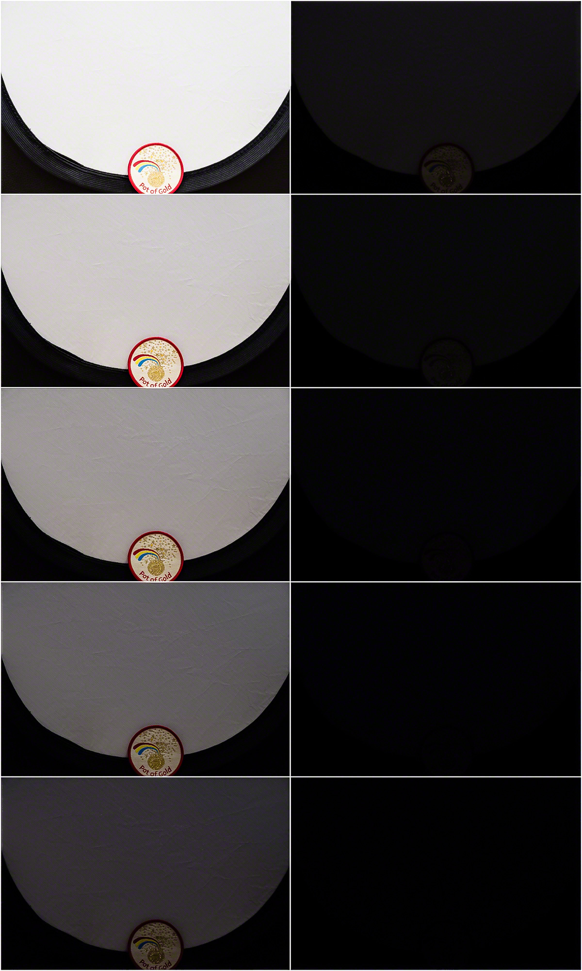
In order to turn a properly exposed, non-clipping, bright white background to black it will need to be under-exposed. How much may depend on the contrast of the light used and the reflectivity of the surface, but is likely to be between 6-8 stops. In the example at left, the bright white, non-clipping exposure was 1/4s at f5.6 and ISO 400 whereas the dark exposure was 1/500s at f5.6 and ISO 400, some 7-stops less.
The chart at left shows the incremental reduction in exposure, one stop at a time, of a small white Lastolite reflector. Although, at a distance, a 5 stop reduction looks adequate, you can clearly see the reflector in the image on the computer.
The ambient exposure needs to be reduced substantially in camera, and the subject re-illuminated, to compensate for the reduction, usually with flash. Shooting in manual, most flashes have a range of 1 to 1/64 or 1/128 power (6 or 7 stops respectively). This may sound a little close for comfort (which it may be), especially when using light modifiers that reduce the flash by 2+ stops. You can also place the flash nearer to the subject if needs be however.
What Can Go Wrong?
When trying to turn a white background black, the re-illumination of the subject has to be specific to the subject. In other words, the 7 stops of flash that you add back in must not travel to the background and re-illuminate it as well! This is awkward in smaller studios (or a mostly white painted kitchen as in this case) where flash bounces round the room increasing the ambient again.
Mitigating The Re-Illumination Light Spill
There are two main ways of managing light spill, firstly to manage the direction of the subject re-illumination light (so that it misses the background) and secondly using the inverse square law in setting the flash to subject and subject to background distances. In the smaller studio it may also be necessary to mitigate bounced spill by using flags or black reflectors or covers.
Managing Light Direction and Spread
Two main strategies will help here. Firstly, avoid front lighting if you can because the spill will necessarily hit the background. Try and use side lighting or lighting from high up and to the side so that the spill-light travels past the side of the background or down to the ground. Secondly, use light modifiers to narrow the direction of light rather than having light going off in all directions. Choose your modifier based on the following priority list (worse to better) for best directionality.
- Shoot through umbrella
- Bare flash with wide spread
- Shoot back umbrella
- Bare flash with narrow spread
- Softbox
- Deep Softbox
- Softbox with grid
- Grid Spot
- Snoot
Finally, you may need to control spill by reducing reflections from large reflective surfaces. This can be achieved by using large black panel reflectors (or non-reflectors) or covering with black sheets or a roll of black paper. Obviously, if you have these to hand, I have to question why you are trying to turn a white background black in the first place!
Inverse Square Law
What is it?
What is the inverse square law, and how does it help? Basically the inverse square law states that the intensity of light from a source falls off with the square of the distance from the light source. So if the intensity of light is X at 1m from a light source, at 2m it will be X/4 and at 3m it will be X/9 and at 4m X/16. This has some interesting implications for the photographer. Firstly it means that every doubling of distance from the light source delivers a 2-stop fall in light. So, for an example, if you had a subject lit by flash at 0.5m then at a background set at 4m there would be a reduction of 6 stops of light, and at a background set at 8m an 8-stop reduction. A small increase of flash to subject distance from 0.5m to 1.0m doubles the necessary flash to background distance to get the same reduction in light (namely 8 and 16m respectively – better order your new kitchen extension now!!).
How is it Used?
Secondly, and perhaps rather confusingly, the proportional light fall off with distance is greater close-in than it is far out. This is because the light intensity is the reciprocal of the distance squared so that, for larger distances, the difference between the fractions is necessarily less than for shorter distances. So light intensity at 2m is a quarter that at 1m, ie a 3/4 (0.75) reduction between 1m and 2m. At 4m the light intensity is 1/16 reducing to 1/25 at 5m. So the difference in intensity between 4m and 5m is 9/400 (0.0225). This is useful where subjects are at different distances from the flash. Moving the flash back to say 5m from the subjects would mean that there was virtually no difference in illumination between subjects at 4m or 5m (for instance in a wedding group shot).
Other Confounders
Managing light spill can be harder where you have, for instance, a white tiled floor, or a low white ceiling. The floor can be covered in extremis (beware the trip hazard though) but there is very little you can do to mitigate a low white ceiling.
Production Images and Results
Here is the setup for this shoot. You get some sense of the restricted space and can see the camera, subject and strobe positions clearly.
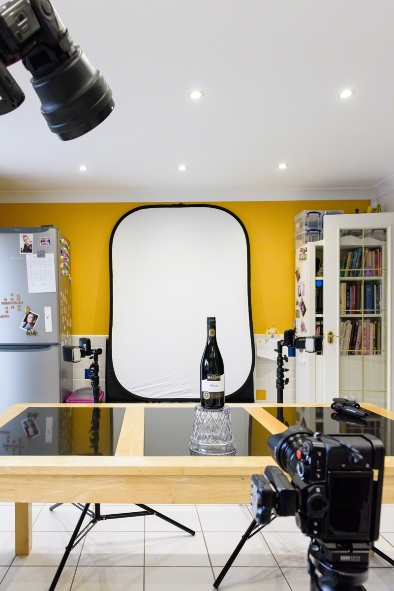
Kitchen Studio..
Post Processing
The three wine bottles shown below were all straight off the camera card and, apart from a small crop, completely unedited! So I’d have to say that the morning spent trying to turn a white background black was a complete success. I’m bound to also say, though, that I’ve no intentions of abandoning my beloved black velvet Lastolite panel background anytime soon.
Equipment Used
Equipment used was a Lastolite large panel Black/White reversible background, a Lastolite black velvet background to control spill (out of shot), 3 x Nikon SB900 Speedlights, 3 x Bowens Light Stands, assorted cold shoe clamps to attach the Speedlights to the light stands and a Gary Fong Collapsible Snoot with Power Grid for the key light. For convenience I was using 3 x Pocket Wizard Flex-tt5 radio triggers, with the mini-tt1 and AC3 controller on the camera. As you can see there is much white and silver in this room to bounce spill light around. The main kitchen lighting is daylight balanced and camera left sits a large kitchen window and patio door.
Camera and Flash Settings
The eventual camera settings were ISO 200, f11, 1/125s. The key light was set to full power and the rim lights adjusted to give a pleasing result at a much lower power (around 1/32).
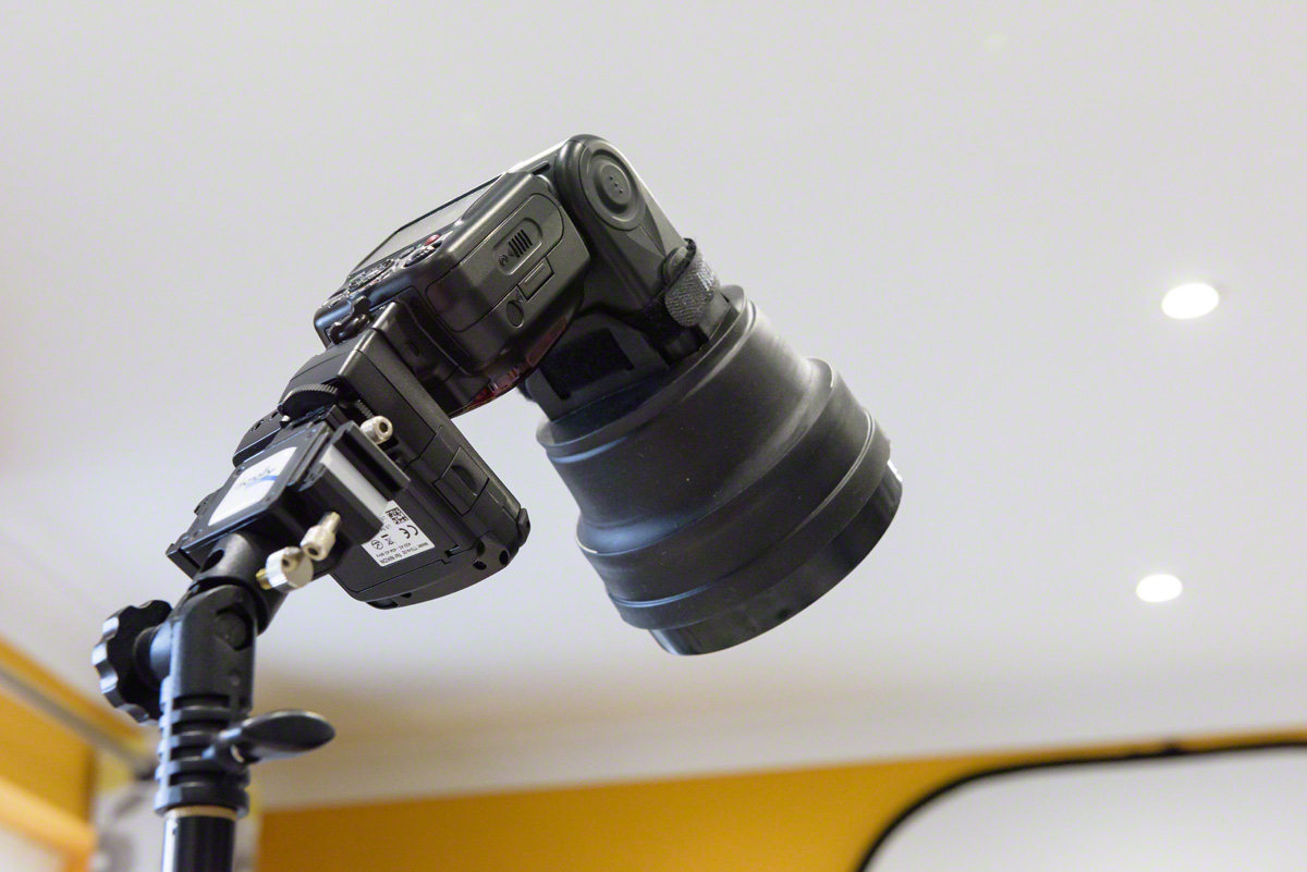
Key Light with Grid Fitted..
Use of the kitchen studio was only possible in the absence of other family members, so thanks also to them for leaving me with the house for the morning too. I think that it must be so lovely to have a permanent and dedicated studio where you are not hunting round the house for your equipment because it is all in one place. Or having to move chairs and furniture to create sufficient space. Perhaps when I retire.. You can only dream I suppose..
I feel a large man-shed coming on..
Final Thoughts
Small Kitchen Woes..
To pull this off in my kitchen studio I had to use all available space and had to keep the subject size down as I was rammed against the range cooker. You can’t see it in the production shot, but I had to manage some light spill with a large black panel reflector out at camera right. For me this was a technical exercise, just to see if I could do it. I have tried without success previously as I could not manage the light spill effectively enough. The subject to background distance, for me, was only about 3m so control of light spill was essential as I couldn’t afford to only rely on the inverse square reduction.
Controlling the Spill..
If I had needed more control of light spill, I would have thought about reducing the light from the white floor tiles and used flags on the rim light flashes to stop light getting onto the ceiling. Finally it might have been necessary to use another black panel reflector on the wall behind the camera to further reduce spill.
Could do Better..
As a technical exercise, I have added to my own difficulties by using my Fujifilm XT-20 travel camera instead of my Nikon kit. I don’t have a full flash setup dedicated to this camera system so I was working with manually. I was, however, very pleased to find that my flex-tt5s and SB900s could be used on my Fujifilm XT-20, controlled by the flex-mini tt1 and AC3 controller combo on camera in the usual way. The only concession was that I had to drop the shutter speed on my XT-20 to 1/125s in order to get reliable syncing. The XT-20 maximum sync speed is 1/180s which I am confident would have worked ok with optical syncing, but didn’t with the radio kit. Since my Flex kit is for the Nikon, I’m pleased that I was able to use it on the Fuji at all, so this was a small sacrifice to make.
Cheers,
R.

Jul
02
Shooting Macro
I love shooting macro, though inspiration can be a little tough to find at times. I already have a 105 mm Micro Nikkor, but had been thinking about a longer focal length for some time. After some research, it seemed to me that, rather than buying the 200mm f4 Micro Nikkor which has a 20 year old design, I’d be better off going with the Sigma 180 mm F2.8 APO Macro ED DG OS. My thinking was thus. Firstly it is a faster lens, very sharp and has a good reputation. The 200 mm Nikkor, is also stunningly sharp, and built like a tank, but it is very much a one trick pony. The autofocus is very slow (though satisfactory for things a long way off apparently) and it has a maximum aperture of f4.
Making a Purchase, Checking It Out..
So, at the last but one photography show in Birmingham, I visited the Sigma stand and spoke to a representative. After looking at the lens, and hearing about it’s performance, a purchase was made from London Camera Exchange. It duly arrived, at our local store, about a week later. Had it not been a bank-holiday weekend it would have been even sooner. It’s been superb! Out of the box, the Sigma appeared well made and robust. I fitted a Wimberley Arca Swiss lens plate and set about shooting tethered using Helicon Focus. This revealed an unexpected, yet key, difference with the 105 mm Nikkor.
Bearing in mind that I had always considered the 105mm Nikkor to be an excellent lens, I was not prepared for the stunning absence of chromatic aberration. It’s not that the Nikkor is particularly bad, it’s just that the Sigma has no chromatic aberration. None at all. At least, I haven’t come across it yet. There must be some somewhere mustn’t there? But the visible difference was remarkable. With the same subject you could see the artifacting on the Nikkor but not on the Sigma. Amazing!
Choosing Between Macro Lenses
Back Garden Birds, Hide, Backlit
Choosing a lens for shooting macro requires a little thought. Firstly, what do you tend to shoot? If it’s wildlife, there is something to be said for a longer focal length to keep you more distant from your subject. This is not the only relevant factor however. Most of my outdoor shooting uses available light, sometimes with a reflector or torch to provide fill or dimension. The physical length of the macro lens I use makes little difference in this scenario, but if I’m to use flash then I need to consider two other issues.
Flash and Macro Lens Choice
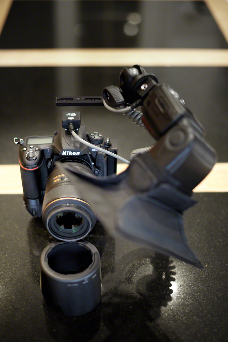
Clearly, for macro shooting with flash, the length of the lens itself makes a big difference to the type of flash you might use on camera. Will the flash be a Speedlight on a flash bracket? If so, a 105mm or 150mm lens will be more useful as you can get the flash nearer to the subject. The flash bracket can reach over the lens (as opposed to be in the lens’ shadow). Here I’m using a Custom Brackets CB Folding-T folding flash rotating bracket to hold an SB900, with a Neewer SB1520 small softbox attached, to light a subject from above and to the side.
Were I to attempt this with the Sigma 180 mm F2.8 APO Macro ED DG OS I’d be out of luck. On a D500, with the APSC lens hood extension, it is approximately 330 mm in length compared to the 190 mm of the Nikkor (or aprox 115 mm without the lens hood).
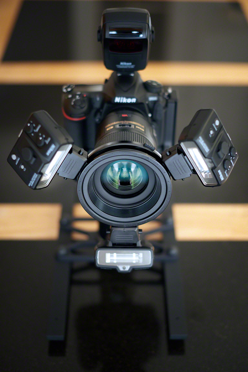
R1C1 macro flash kit on a Nikkor 105mm f2.8
Using a Nikon Speedlight Commander R1C1 Macro Flash
If you are going to use the Nikon Speedlight Commander R1C1 Macro flash, for instance, you also need to bear in mind that there is no adaptor ring available in the 86 mm filter size of the Sigma 180 mm. You have to use the SB200s off lens in this case. Personally, I felt this was an inconvenience rather than a deal breaker, because when I work with flash it is usually in the studio and I can easily use stands for the flash.
Multi-Purposing a Macro Lens
It occurred to me that I have used my 105 mm Nikkor as a portrait lens in the past, ideal on a full frame camera. Would a longer prime be useful for some of my larger birds in flight work, for instance Osprey at Rothiemurchus? With a working focal length of 27o mm on a crop sensor camera (my D500), it might be a useful alternative to using my D810 with my 300 mm f2.8 (which is a much larger lens). This could be ideal for the lower light situations pre-dawn when the D810’s ISO performance is less suitable.
Lower-weight, and shorter minimum focal distance, make it a good choice for ad-hoc wildlife appearances closer to the hide.
Depth of Field Calculations
Sigma do not supply depth of field tables for shooting macro with their lenses, so ascertaining depth of field for close up work is not straightforward.
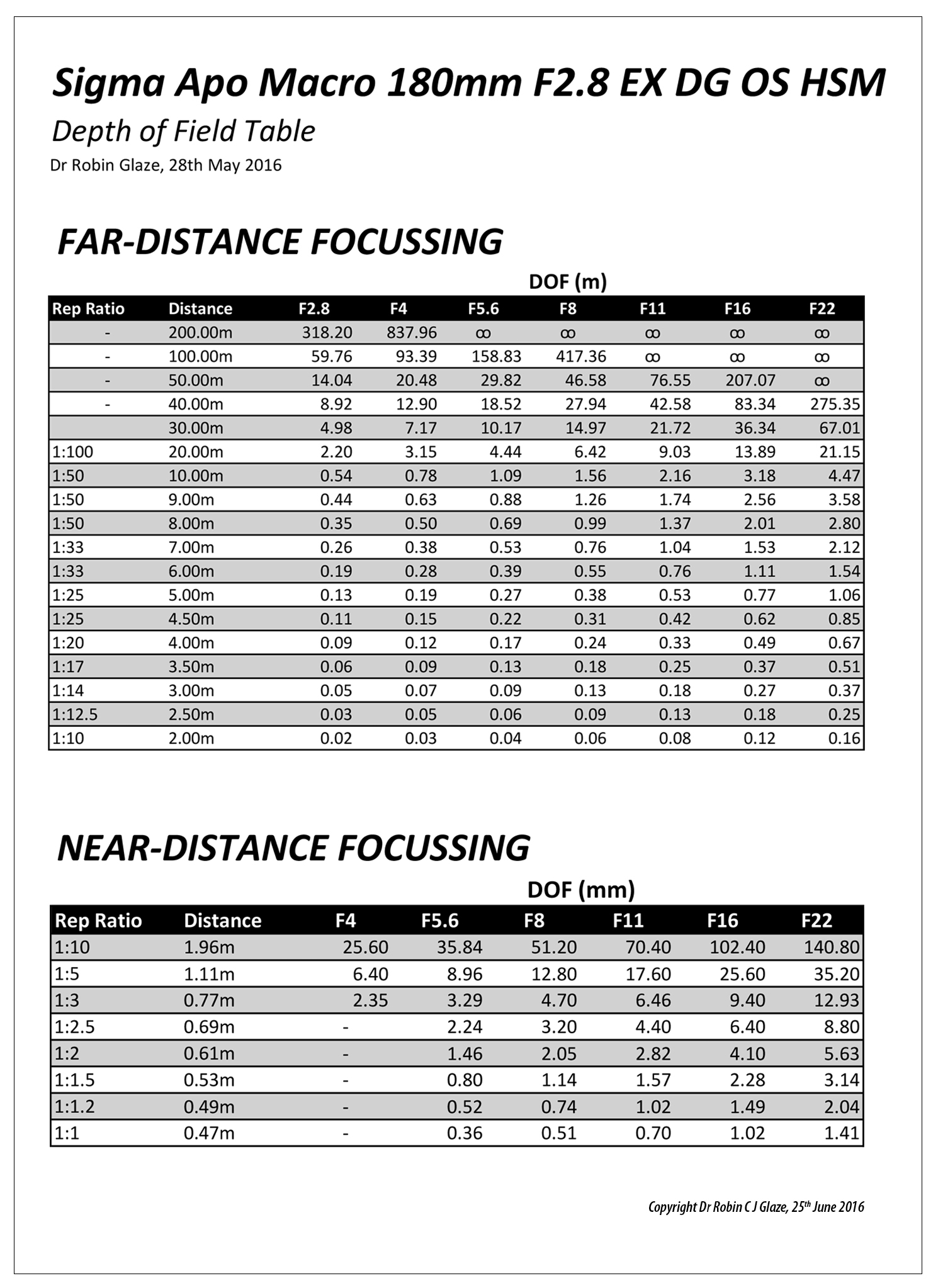
Doing the Math..
Some research was required to find out how to do the DOF maths, but with an Excel Spreadsheet I was able to produce a depth of field table. This has helped me appreciate how some of my shots might work – pre shutter release.
I guess, ultimately, if you take enough shots, you learn from experience, but knowing whether to make a virtue out of a wide aperture shot’s limited depth of field can be a little thought provoking if not enough image is sharp. I never mind taking many different shots whilst I’m out in the field, on the basis that one of them might be spot on. When I can get them onto the computer, It’s easy to see how I did, but I’d really rather know how to take the image work with a single click.
Lateral vs Longitudinal Chromatic Aberration (CA)
Types of Chromatic Aberration
Chromatic aberration occurs because shorter wavelengths of light (blue) are refracted (bent) more than longer (green and red) wavelengths of light which are refracted less. There are two types of chromatic aberration. Lateral (or transverse) and Longitudinal (or Axial).
Lateral CA occurs when all the colours are focussed at the same plane, just not aligned. R, G and B light are focussed sharply, but side by side. In Longitudinal CA, the colours are not focussed at the same plane, they are superimposed with blue in front of green in front of red. To observe this, Lateral CA causes coloured fringes around objects of high contrast, whereas Longitudinal CA causes patches of colour (ie. the most in-focus colour predominates).
The 180 mm Sigma Macro lens is particularly good with Longitudinal CA, you do not see colours change as you move up to, and then through, the focal point for high contrast details. Longitudinal chromatic aberration is very noticeable in the Nikkor 105 mm in comparison.
Recent Images
Jan
09
Building a New PC
Photography can be an expensive hobby these days! Whilst it is perfectly possible to shoot small jpegs and to print them at a booth in your local store, most serious photographers are shooting RAW images in large numbers, and using Photoshop CC 2015 and Lightroom (or similar) to edit them. If you do any video work, or perhaps need to do some print work with InDesign, suddenly you need acres of storage space and a high-end workstation to make the process flow. 5-years ago, in another Christmas project, I built my first decent PC using an SSD for the operating system and the, then current generation of, Intel i7 chip. This has served me very well, even to the point of adopting Windows 10, but the final nail in the coffin was the recent update to Creative Cloud 2015. These days I use plugins extensively (On1 and the Google Nik Collection) but the combination was only useable with extreme patience! So time for an upgrade. Time for me to set about building a new PC.
Lots of things change over a five year period, in life as in PC tech. My partner in crime Geoff keeps in touch with the hardware developments and is an avid subscriber to Micro Mart Magazine. He put together an initial specification, as the basis for discussion, and together we researched further and finessed our individual computer builds. I’ve been using a Dell monitor for the last 8 years, and it’s been great, but I also took the opportunity to upgrade to a slightly larger 27 inch model with 100% Adobe RGB (and sRGB) colour (Dell UltraSharp Premier Colour UP2716D) on the grounds that it would be better for my eyesight as well as my colour correction. Apparently the colour profile is fabulous straight out of the box. We’ll see and I will comment further once I’ve a few hundred more hours photo-editing under my belt.
The Components
Building a new PC is not a cheap way of getting a good computer, but it is the perfect way to choose precisely the specification, and the supplier of the components, that you want for your build. You need leave nothing to chance! My list of components was, as follows:
| Asus X99-Deluxe u3.1 Motherboard |
| Intel i7 5930 Processor |
| 32GB: 4*8 GB DDR4 Memory |
| Samsung Pro 500Gb M.2 SSD |
| 4TB Seagate Hybrid HDD * 3 |
| Corsair RM 1000W Fully Modular 80+ Gold Power Supply |
| ASUS GTX 970 Geforce Graphics Card |
| Samsung DVD Writer SATA |
| Fractal Define R4 Case |
| Windows 10 OEM |
| Noctua NH-Ul4S Slim U-Series Single Tower CPU Cooler |
| Wireless Keyboard and Mouse |
| Monitor Dell UP2716D |
The Suppliers
The order was fulfilled promptly by Amazon, Scan and Ebuyer without fuss, though the packaging on the Dell monitor was water damaged on arrival, but the contents were dry and untouched. Close to Christmas, it did not seem worth taking the risk of sending it back and risking not being able to complete my build during the holidays, so I kept it.
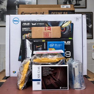
The Grand Unboxing..
It’s a little beyond the scope of this article to describe the full detail of my build, but I will share some of the highlights. Firstly make a big pile of boxes and admire. Next unwrap the goodies and make sure you have everything you need for your build, and that you have looked at the Motherboard manual to know where the different connections are for the Power supply, Fan headers, SATA and SATA Express ports etc. Make sure you also know which memory slots to use if you aren’t using all of them, and finally make sure you understand any restrictions on the PCIe slots for peripherals.
The next thing to do is to think really hard about the order in which you want to do things in order to make it easy for yourself. For instance, it’s easier to fit the processor to the motherboard before you fit the motherboard into the case. Also, when you’re building a new PC, it is easier to fit some of the cables to the motherboard before you fit it inside the case. Which cables to fit depends on your specific board configuration and also your particular case. The Fractal Define R4 is an excellent case. It’s very well made and quite a bit wider than the Cooler Master I used for my previous build (I could hardly fit the GTX 970 in that case) so there is more breathing room than in some boxes. Nevertheless space will be tight in some scenarios, and you don’t want to be forcing cables onto headers as this will stress the motherboard and lead to breakages.
Putting It All Together
It was fun to photograph the various parts as a memento of the build. The Intel i7 5930 Processor was gorgeous to behold, and the Asus X99 Deluxe u3.1 Motherboard looks so stylish that it begs to be lit and viewed through a transparent case (not that I’m keen on that sort of ostentatiousness usually, but you can see why people do that stuff).
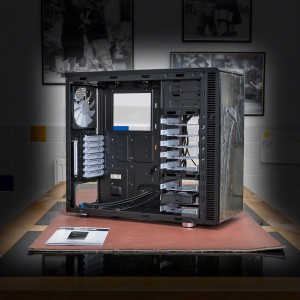
Fractal Define R4..
Here is the case with the sides removed. Apologies for the industrial strength vignette, it does focus you on the case though. The R4 has some lovely detailing with it’s white fans and drive bays etc. It comes with a box full of screws and a manual leading to an easier build experience.
Another benefit of the R4 is that you can fit extra fans in the top (2 fans) and side (1 fan) should you need them for extra cooling. It’s vital to ensure a stable cooling environment if you are minded to overclock your system. The speed of a processor depends on how many things it can do linearly per second (Clock Speed), and how many things it can do in parallel (Cores and Threads). The overall speed of the processor also depends upon the speed at which it can write out to, and retrieve from, it’s supporting memory systems so the RAM bus speed is also crucial. So what is clock speed (and thus overclocking)? Clock speed, or rate, is usually given as a frequency in gigahertz (GHz) these days and it’s the number of times a second that a processing step occurs. Some programming operations can take more than one step so there isn’t necessarily a one to one relationship between the clock frequency and the execution of lines of computer code. As far as graphics processing is concerned though, the faster the better, and the more parallelism the better (at least in graphics cards and some video editing software).
More About the Motherboard
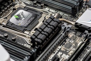
Asus X99 Motherboard..
Asus are manufacturing a range of motherboards with the so called X99 Architecture. So what does this mean? The new intel Core i7 processor and intel X99 chipset were designed to provide the ultimate desktop PC platform for extreme gamers, enthusiasts and content creators. It has special features which enable it to be overclocked and give great performance for gaming and digital content creation. This includes 6 and 8 core processors on the, so called, LGA2011-v3 socket (that’s an LGA2011 without a processor fitted on the left). Performance is boosted via Intel’s Turbo Boost 2.0 technology and Intel Hyper-Threading technology. As well as ultimate performance, the X99 architecture also maximises input/output and storage capabilities. The Intel i7 5930 processor used here (6 Cores), for instance, and it’s big brother the i7 5960 (8 Cores) have 40 PCIe (PCI Express) Gen 3 lanes, 10 SATA ports (for your disk drives), 14 USB ports (a key factor for me) and 20 MB of Smart Cache. Intel Rapid Storage technology delivers excellent storage performance and features to improve system responsiveness.
More Memory
The new Core i7 processor with the Intel X99 chipset also gives us quad-channel DDR4 memory at 2133 MHz that can support up to 4 unbuffered dual inline memory modules per memory channel with a max DRAM density of 4 GB and 8 GB. So this board can have up to 64 GB of memory in total!
Content Creation
With up to 40 lanes of PCI Express 3.0 the X99 platform gives you the flexibility to plug in up to 4 discrete graphics cards to provide dramatically reduced editing time for RAW photos and HD video. Given that I have a spare GTX 970 now, I may add that into my build once I’m happy that everything is running in a stable setup.
Unlocked Processors
This means that the user can performance tune the processor and memory frequencies themselves, without having to run any other part of the system above specifications (and hence risking, for instance, heat damage from large voltages).
Peripherals
The X99 chipset has integrated USB 3.0 support and the Rapid Storage technology allows the full Serial ATA (SATA) interface to go up to speeds of 10 Gb/s in keeping with the next generation of fast solid state drives. There is also a Rapid Recover technology that helps users to recover their data and return their system to an operational state and a Dynamic Storage Accelerator which speeds up the performance of your SSDs by dynamically adjusting the system power management to give up to 15% performance boost.
Specific Asus X99 Deluxe u3.1 Benefits
On top of the X99 specification, Asus have built in a number of other benefits
- Easy-fit 10 Gb/s USB 3.1 type A card
- 3×3 (3T3R) 802.1 ac Wi-Fi, up to 1300 Mb/s
- Fan Extension Card
- Dual 32 Gb/s ultrafast M.2 x4 (onboard plus PCIE add-in card)
- 5-Way Optimization by Dual Intelligent Processors. One click overclock and cooling
- Crystal Sound II (a fine implementation of the Realtek ALC1150 8-Channel High-Definition Audio CODEC)

All the I/O You Will Ever Need..
Why Wi-Fi?
What on earth was I thinking when I specified Wi-Fi for a Desktop Computer that would never leave my office next to the superfast broadband router cable? Actually it was just an indulgence in the long term, but very necessary at the point I was doing the build. My office is far too small to build a new computer in and I couldn’t afford, at the point I did this build, to be without a computer. Wi-Fi lets you connect to the internet and get on with your install, until such time that you have a stable setup. I have known network cables to fail sometimes, usually when you haven’t got a spare one to hand and the shops are shut! If that ever happens, I’ll have a very useable setup using wireless.
The Build
Install the Intel i7 5930 into the LGA2011-v3 Socket
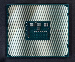
The Connected Side of an i7 5930..
I haven’t tried to count the number of pins in an LGA2011-v3 socket, or the number of gold plated connectors on the back of the i7 5930, but there look to be, quite literally, hundreds. In fact, apparently, the clue is in the name, there are 2,011 contact pins in the socket. The Asus X99 Boards have extra pins to help them manage the overclocking functions, which, I suppose, must mean that there are more contact patches on the i7 Haswell-E Processors than there are in the standard v3 socket.
Ok, I admit it, my curiosity has been piqued. How many contact patches are there on my i7 5930? I did count them in the end after all. There were 2,092 including the 8 patches in the inner square, and excluding the triangular patch that tells you which way round the processor sits in the socket. How did I count them? I used Photoshop’s count feature (once I’d located the count tool which is not shown by default in CC 2015, presumably because hardly anyone uses this very useful feature much these days).
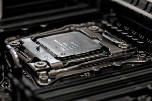
i7 5930 Processor in-situ..
To insert the processor you lift up the two retaining springs which allow the hinged cowling to swing up. You remove the plastic pin cover and then place the processor with the triangular marker aligned with the mark in the socket. Next you replace the cowl and the springs (which do require quite a strong force to replace).
Next simply admire to taste. The top of the processor looks just as cool as the contact face after all. You won’t get to see this again (hopefully) because soon we are going to have to install the heat-sink, which first requires you to place a dollop of thermal paste on top of the processor so that you don’t get a metal to metal contact with the heat-sink. Things have moved on since my last build, the heat-sink is no longer a small fan assembly atop the processor, but now a massive radiator with a fan the size of the extractor unit in my en-suite bathroom. No-seriously, it’s pretty much that large!! Or a water cooler of course. I used the Noctua NH-Ul4S Slim U-Series Single Tower CPU Cooler.
Fitting the Motherboard and Power Supply
When building a new PC, to fit the motherboard, you first screw in the mounting posts to the relevant pre-threaded holes in the casing assembly. Next, as mentioned above, you may wish to fit a few of the necessary cables to the more difficult to reach motherboard headers and SATA cable sockets.

SATA and SATA Express Sockets..
Then you drop the motherboard into the case and fix carefully by screwing through the motherboard into the mounting posts that you previously secured. These fixings also serve to earth the board to the cabinet in several places.
Next comes the power supply. In this case a Corsair RM 1000W fully modular 80+ gold power supply. It’s worth investing in a high quality power supply because of the extra stability of the voltage supplied, and a decent wattage, particularly if you plan to have more than one graphic card, or to expand to the max. Generally the fan faces into the casing when fitted and vents waste heat out of the back of the unit.
Fitting the CPU Fan
Noctua are recognized as making the best fans, and many people swap out their case fans for Noctua ones. They are very quiet and provide a constant pressure. The radiator towers can be single or double thickness with one or two fans (push, versus push-pull). I have it on good authority that for the thin tower version adding a second fan makes very little difference to the CPU temperature (Linus Tech Tips).
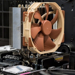
The Beast..
I’m using the Noctua NH-Ul4S Slim U-Series Single Tower CPU Cooler here, and even this seems massive compared with previous fans I have used. I’d be grateful for an extra fan this size in my en-suite bathroom! This fan gets great reviews for running silent, and for it’s cooling power, so it is ideal for a machine that will be overclocked. It may be that a water-cooler would be better still, but that seemed overkill for this application. Somehow it seems a bit risky to place a water system into a box of electrical components? I’m sure they must be durable and safe though.
The other advantage of this single-tower fan is that it allows easy access to the memory modules which can be easily fitted and removed without having to move the cooling assembly. The fan itself is held in place with easy to remove clips to further improve access. Of course there is another benefit to having a second fan on your cooler tower, which is to provide built in redundancy so that, should it fail, your precious overclocked system will have an extra margin of safety, but at the price of (purchasing an extra fan, obviously) a small amount of extra noise.
Fitting a CPU cooler requires a small blob of thermal compound, and this comes supplied with the Noctua NH-Ul4S Slim U-Series Single Tower CPU Cooler, along with all the other bits and bobs to fit it with.
Memory
In this build I’m using 32GB (4*8 GB) DDR4 Memory in the form of Corsair Vengeance LPX 2666 Mhz DDR4 which comes in at a great price point. It’s Quad Channel and Intel XMP certified. So what does that mean? Vengeance LPX memory is designed for high-performance overclocking. It uses an aluminium heat spreader for faster heat dissipation and it’s low profile design fits into most microATX and MiniITX systems.
Intel Extreme Memory Profile (XMP) allows you to overclock RAM including compatible DDR3 and DDR4 memory to perform beyond its standard specifications. This is designed to help enhance the gaming features built into other Intel technology.
Four channel? This just means that for any given amount of memory (32 GB in this case) you can have a kit that fits that memory into 4 memory card slots (or channels) on the motherboard in order to get the fastest throughput of data. The Asus X99 Deluxe U3.1 motherboard has two sets of 4 memory-bus slots for this purpose.
How does XMP work?
Predefined and tested Intel XMP profiles can be loaded via the BIOS, or a specific tuning application, through the computer’s operating system. Intel has developed a certification program for memory vendors to test their products for compatibility against the Intel Extreme memory Profile. Intel provide an Extreme Tuning Utility to help with the overclocking process. Asus motherboards come with the AI Suite 3 which serves the same purpose.
Fitting the Graphics Card
The ASUS GTX 970 Geforce Graphics Card slots into one of the 5 PCIe 3.0 slots, then gets power from the power supply. For building a new PC the Motherboard Manual guides you on which slots to use according to whether you want to use a single or multiple graphic cards, and a special linking cable is supplied to sync the cards together if multiple cards are used. Slot 1 or slot 3 would normally be used for a single card, and slots 1 and 3 for a dual card setup. Slot 4 is added for a triple card setup.
Fitting the Disk Drives
When building a new PC, this is fairly straightforward. I have a single M.2 memory module (Samsung Pro 500Gb M.2 SSD) and 3 hybrid drives(4TB Seagate Hybrid HDD) to fit. The M.2 SSD slots into the Motherboard, vertically, with a special bracket, and the 3 hybrid drives go into 3 of the 8 drive bays using the provided screws into the removable mounts. It’s best not to tighten these much as they pass through rubber grommets to provide a less rigid mount.
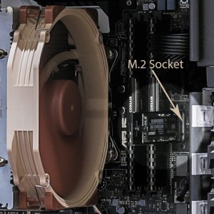
M.2 Slot with SSD Card in Place..
So why choose three 4TB spinners? I’ve been keeping my photos on two external 4TB USB drives recently, and JPEG backups of my favourite images on my Dropbox Pro Account. These drives, one for storage and the other for backup, are 60% full now, and have been quite slow with my D810 files in Lightroom. My old PC only had USB3.0 so, with the optimised USB 3.1 I was hoping for a marked increase in speed. I’m doing more and more photography with my D810, so I reasoned that it’s time to move my storage back to fast internal drives (one for storage and one for backup) for the new stuff. The third drive is for all my non-photography stuff and the backups for that are on yet more external drives. It’s not a perfect strategy, but it’s good enough for what I’m needing to do.
There’s good future proofing with the ASUS board. As SATA Express drives become available I can upgrade to those without shedding the drives I’ve got fitted at the moment, and the spare M.2 slot, via the PCIe card, means that as super-fast SSD storage comes down in price and the drive capacities rise, which they are bound to do, over the next year or two, I can consider adding a further SSD without prejudicing anything else. The future expandability looks very good indeed.
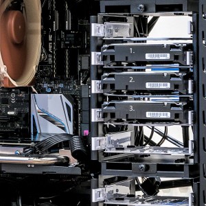
3 Spinners All in a Row..
Each hybrid drive needs power and a data connection into the SATA ports. These come in at the back, and space is a little tight, so you need to use an angled SATA cable to avoid any pressure being put on the connection when the side is replaced on the case.
According to Seagate, “SSHDs fuse the strength of SSD and HDD into one affordable and powerful device”. This gives you the combined reliability of both in the hybrid drive product. These drives have 4TB of hard disk storage and a very decent 8GB of fast integrated NAND Flash. Basically, the hybrid drive works out which files you are using frequently and uses the SSD to cache them without you having to do anything. As you are probably aware, SSDs have a limited write life, they hate being written to, but you can read from them as many times as you like. The main wear factor for a spinning disk (HDD) is starting them up and shutting them down, though reading and writing have small but equal wear overheads. The benefits of SSD are that they are resistant to fragmentation in the sense that it matters not where various pieces of file reside in terms of speed of access, whereas on a hard disk drive fragmentation is problematic and slows access times down dramatically. HDDs are better for storing large amounts of data, but access is much slower. So in terms of wear, caching data to the SSD cuts some wear and tear on the HDD. You can check out the detail of the technology here.
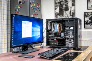
Testing..
This is where the rubber meets the road. Plugging in the monitor and the power supply and pressing the on button! No problem, it all worked.. Next install Windows 10, setup the wireless connection and update everything. Install the motherboard and graphics card drivers and then the hardest part of the build is installing all of the software and copying over all my data from the internal drive of the outgoing PC. Fortunately, with 8 drive bays, it was a simple matter to remove my data drive from my old PC and install it into the new one for a rapid copy and paste. Lots of my software is licensed however and needs to be deactivated from the old PC before it can be activated on the new build, but the Wi-Fi made this easier than it would have otherwise been because I could run both PCs at the same time.
Testing and Installing Windows 10
And herein started the real ordeal. I had several problems which involved corruption to vital windows files that were not that easy to fix, and, for stability sake, I ended up doing 2 complete installs before everything worked as it should. There is a bios update for the Asus board which will undoubtedly improve stability and I will flash the bios with the update once I’ve been running the new build for a few weeks and feel I really understand the stability issues.
Overall Impressions
I’m very pleased with the new build and I will certainly be keen on building a new PC in the future. Things I like about this build:
- It’s much quieter than the old one, so much so that the hum from my powered 50w Genius Multimedia Speaker System became very noticeable and distracting. It’s been necessary to research an alternative and in the end I went with a pair of Audioengine A5+ (powered) Speakers. These play very nicely with the Crystal Sound II on the Asus X99 Deluxe U3.1. It’s said that the Audioengine D1 24-Bit DAC/Headphone Amp can improve quality still further by circumventing the built-in Crystal Sound System, so I may look into that further at some point.
- The Dell UP2716D Monitor is a real step up with an excellent built-in profile straight from the box. It’s sharp and clear with excellent colour and a decent fit for my desk. Much less tiring for my eyes.
- USB 3.1 is noticeably faster on my external WD 4TB drives, making Lightroom much more useable even on my huge back-catalogue of photographs.
- I’m loving the increased performance of Lightroom and Photoshop CC 2015, including my plugins, all in all it’s much more useable now.
- I have learned lots about the up-to-date technology in general and building a new PC in particular. Next time I might go with a transparent case and multi-coloured lighting plus a CPU water-cooler!!
Problems
There have only been minor issues so far. Windows 10 didn’t want to recognize my old HP LaserJet P2200. I’m not sure what the problem was at its core, but it was resolved by switching the USB lead into a USB 2.0 port instead of a 3.0.
Until next time,
R.

Aug
26
Photographing Osprey
Birds of Prey / Field Craft / Garden Birds / Nikon D4 / Nikon D810 / Photography / Wetland Birds Posted by Robin
/
2 comments
Photographing Osprey

Full Gas: Osprey Leaves with Trout..
I’m just back from an osprey shooting workshop in the Scottish Highlands. Photographing osprey is a new experience for me, and there are a number of differences in approach to assimilate. But first let me describe the workshop in general terms, before moving into the particulars of the photography, and telling you a secret or two about my personal journey in photography!
Images In Nature
My long-time shooting buddy Geoff and I had booked the Osprey Workshop with Images In Nature earlier in the year. Images in Nature, run by Lee Mott, offers small group nature photography workshops and tours. We stayed in the Osprey Hotel where we were very well looked after by proprietor Sue and her husband John. Lee is a hugely personable, experienced and knowledgeable photographer. He talked us through what to expect the night before, showing us pictures of the venue, describing the hides and, of course, discussed camera settings and the itinerary.
Itinerary and Venues
Photographing 0sprey involves an early start as you ideally need to be in-situ before sunrise. We were to meet outside the Osprey Hotel at 4:40 am and drive the 11 miles or so to the Rothiemurchus Estate in the Cairngorms National Park, Aviemore. The purpose built hides are based in the Rothiemurchus Fishery where they look over a purpose built pond, well stocked with rainbow trout, for the osprey to dive for and catch. You can book the hides at Rothiemurchus independently if you wish, and the Wild Scotland link gives you a sense of what is available. I can, however, unreservedly state that these are the best designed hides that I have shot from in the UK.
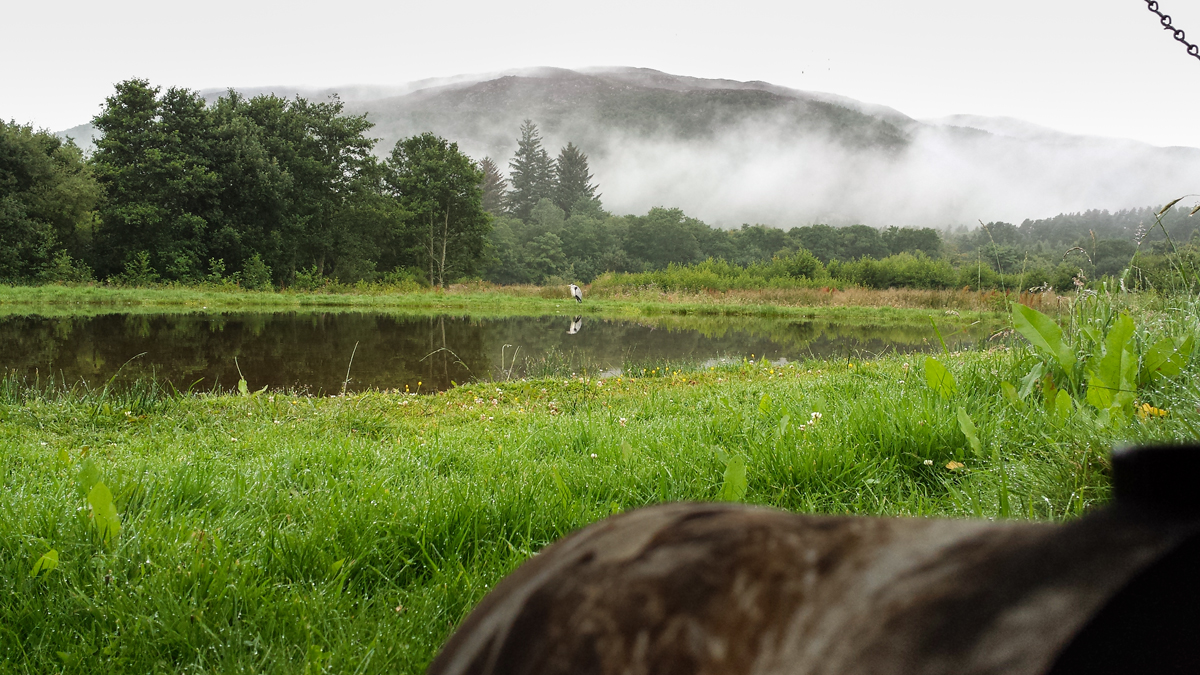
View from the Hide..
On arrival at the fishery, we had a quick coffee and were installed within the hides by 5.30am. There are 4 hides around the fishing pool. The best hide choice depends on the prevailing wind direction because the osprey prefer to take off into the wind (as it helps with lift) and, hopefully, it also helps the photographer to be positioned to see the bird moving towards the camera rather than away from it. During our time at Rothiemurchus the conditions were very still, so we picked one of the middle hides to see what happened. The scenery is spectacular giving multiple possibilities for decent backgrounds and different shot styles. Osprey are not the only visitors to the pond, we had a visit from a field mouse, a family of mallard, rooks, kingfisher and several heron so there is always plenty going on in-between the drama of the osprey diving shots.
After the morning shoot, it was back to the hotel for a fabulous full Scottish breakfast (thank you Sue) and then back to the Rothiemurchus estate to shoot red squirrel, and more traditional garden birds, in the forest in the afternoon.
Key Technique Issues for Photographing Osprey
There are a number of issues to consider, namely, camera settings, fieldcraft and good lens technique.
Camera Settings
Ok, we are only talking Nikon here (I can’t speak for Canon shooters, but if you do shoot Canon you may find these Arthur Morris links useful – Getting the Right Exposure, Camera Settings, Tele-Extenders).
Autofocus Settings
AF-C priority selection = release. Dynamic AF area 9 points. AF activation = AF on only. AF Point selection = 51. AF Continuous and Focus Tracking with Lock on (3-normal). Back button focus is mandatory (well not mandatory, but certainly a lot easier). It’s only fair to say that Lee disagreed with me on the Focus Tracking setting, which he prefers to be set to 1-short or off altogether. I find that I sometimes lose the focus point on the bird and then my focus snaps to the background, or something in front of the bird, before I can get it back again, losing me time and plenty of good shots. For me Focus Tracking is best left on 3-normal or even 5-long (which I use for my red kite shots). If I had Lee’s experience and skill I could probably get away with 1-short, but that’s the benefit of being a professional, you get loads more practice! Use what works for you. It goes without saying that you will be shooting above a 1/500th second so Vibration Reduction should be set to off.
Aperture, Shutter Speed and ISO
As I have mentioned in my blog before, exposure is a perennial difficulty when shooting birds in flight, especially ones like osprey with an intrinsic high dynamic range against a rapidly changing background. I like to shoot manual for this, and so too on this occasion!
At 5.30am in mid-August it is pretty dark so you are dancing a very thin line in order to get useable pictures. Lee’s, very sensible, approach is to start off wide open at 1/500th second with whatever ISO gives a decent exposure. Clearly you risk subject movement at a 1/500th second but, in a way, this can paradoxically enhance a shot with an osprey taking off from the water because it gives a dynamic sense of movement and action with blurring of the wing-tips and water splashes, but still good potential for tack sharp eyes and fish. As the light improves you can increase shutter speed up towards 1/1600 and then reduce ISO to reduce noise. I tend to make 1/1000th second shutter speed my initial priority and then reduce ISO and increase shutter speed in tandem. It’s a percentage game really. Finally, if the sun comes up (it doesn’t always) you can also increase aperture from f2.8, f4.0 or f5.6 (depending on what lens/teleconvertor combination you have) up to about f7.1 for optimal depth of field. On two of the days we had mostly dull and overcast weather and I never got out of f2.8 on my 300mm Nikkor.
Avoiding blown highlights remains something of a tricky issue, and even shooting manual, you have to take account of changing contrast levels in the scene and leave more leeway as the contrast increases. So in dull flat light you can expose further to the right than you can in bright sunlight for a given exposure reading taken from an average tone in advance. As I have said before, I will often use a patch of grass, but this is not always available, and the direction that it is lit from (and how wet it is) can all give a misleading result. I don’t think there is a hard and fast answer to this. On this occasion I knew more or less where the osprey were going to dive and I used the whole scene to take my initial exposure via matrix metering, leaving 1/2 to 1/4 of the histogram width in leeway (i.e. shooting markedly to the left) according to the contrast in the scene. On other occasions I might use spot metering, it just depends on what’s around to take a reading from.
In the interest of full disclosure, we had a heron at the poolside for the majority of the shoot and this was perfect as a cross check for blown highlights. Still, heron images beats endless photos of an empty perch by a huge margin!!
Lens Choice
The Rothiemurchus setup is really excellent and the birds are fishing very close to you. I used my 300mm f2.8 on my D4 (better for me on this occasion, given the light, than the D810, at least until the sun came out!) without any teleconvertor assistance. This was perfect! In fact, I could probably have used my 70-200 f2.8. The wingspan of the osprey can be up to 6 feet so it is really easy to get clipped wings as they fly past. It may be that a 70-200mm with a 1.4x tc would be the perfect setup to begin with – but hey, I’m addicted to sharpness, so what can I say, I used the 300mm!
Fieldcraft
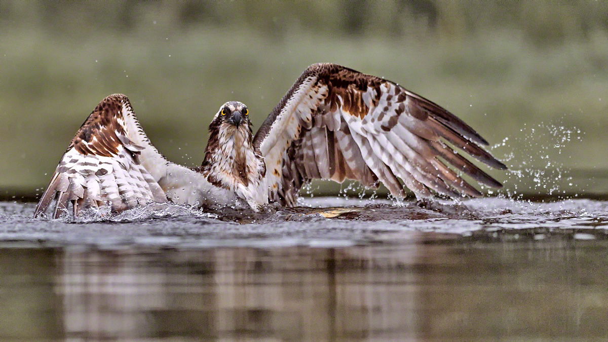
Osprey Landing..
The Rothiemurchus Fishery setup is particularly helpful for photographing osprey because they provide an experienced gillie to spot for the photographers. The gillie watches the osprey and keeps the hides informed on what the osprey are doing via two-way radio communication. The gillie tells you when they are circling over the pond and when they are diving. These guys are all very experienced (we had 3 different gillies over the 3-morning shoot, all excellent) and they don’t waste your time getting unnecessary hopes up. They all know the osprey behaviour well and can often recognize the different birds by sight. The heron can be problematic photo-bombers if they are standing opposite the hides. The gillies would even tell us when it was safe to leave the hide to move them away. It took me a while to realise that this was an opportunity for heron flight shots (but it was 5.30 am after all!).
It’s really important that you do not track, and photograph, the osprey in flight before they dive for fish because this tends to spook them and that bird will not return that day. Luckily, during the osprey season, there are many local pairs of birds with young to feed so you do typically get quite a few opportunities. It is crucial to wait until the osprey has hit the water, then you get focus and keep it as the bird exits the water and flies away with the fish (hopefully). The osprey will be in the water for a few seconds as it has to kill the fish and then manipulate it into a carrying position before exiting. The osprey can move through 180 degrees during this process so it’s worth waiting until you get a pleasing composition in the water, rather than wasting buffer capacity taking shots of the back of the osprey’s head. Once the osprey start to exit the water things start to happen really fast. The wings are enormous and it’s very easy to underestimate how far up the frame they will travel as the bird flies off. Using the central focus point makes sense because you have the fish to worry about at the bottom of the frame and the wings at the top, plus it is the most sensitive focus point in low light.
Gimbal Head Technique
Have you ever had that experience where something you thought you understood (and worked well for you) was completely wrong? Well this happened to me on this shoot, and here’s how! On Friday 25th September 2009, Geoff and I attended our very first raptor shoot with Mark Sisson (another phenomenal wildlife shooter and author). Arguably the very starting point of my journey into wildlife photography! I was using my new gimbal head for the very first time with my 70-200mm f2.8 VRI with 1.7x teleconvertor on my D3, and was having a great deal of difficulty getting a sharp shot! This was a tad disappointing given that I was using my best kit and the raptor wasn’t even moving! Mark came over and suggested I try a few things, namely switching my gimbal head from right facing (as I had it) to left facing. The benefit of this would be that I could lean down on the gimbal with my left hand to steady the shot.
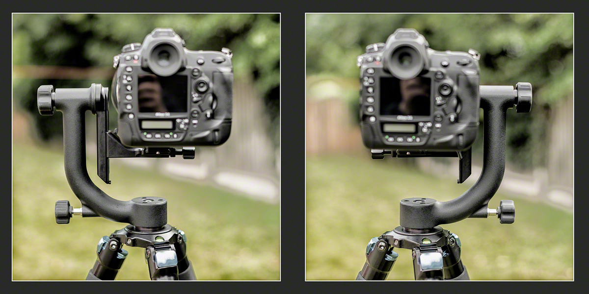
Left-Facing and Right-Facing Gimbal Positions..
This worked out pretty well for me and I’ve used it ever since. I went on to learn that steadying the lens with a hand on top was also useful, and a rubber eyecup to make it more comfortable to press the camera against your eyebrow also helped long-lens technique. Mark definitely put me on the road to better long lens technique, and I’ve been getting sharp shots with very long lenses ever since. But left facing is NOT the best for me, right facing is! Thanks Lee, for pointing this out, not least because I didn’t want to hear it, and you kept going irrespective of my arrogant unwillingness to listen! Here’s the crucial thing. I’m right eyed! This means that I sight with my right eye to the viewfinder but, if the gimbal is left facing, I cannot see a lot of what is coming in from my left-hand side because my open left eye is hampered by the locking ring and upright arm of the gimbal head.
In retrospect it’s all too painfully obvious. I have frequently been reliant on colleagues calling the arrival of wildlife subject matter that I haven’t yet seen. I’ve been amazed that they spot things so quickly when I don’t, I just thought I must be slow, or old, or needing stronger glasses, but actually, there may have been a more obvious reason all along — I was blind-sided by my gimbal head!! Actually, if you think about it, right-eyed people are at a disadvantage anyway because there is more camera body to the left of the viewfinder which tends to obscure the view from the open left eye anyway, so a left facing gimbal head just makes things worse.
I think that the proof of the pudding was that I had no trouble at all sighting a (very small in the frame) kingfisher hovering over the pool, focussing and getting some sharp shots. See them below. The other clear advantage of using the gimbal head right-facing is that you have better access to the lens controls for VR-On and Off and Manual focus adjustment. I found myself more willing to adjust manual focus in the moment as it had been quite awkward with the left-facing setup.
The Images
Heron (the Vital Bit-Player)
Osprey (the Main Event)
Kingfisher (Proof I CAN Still Learn New Stuff)
The Ducks (Who Can Resist Them?)
So, in summary, I had a great time with Images in Nature and would recommend them to anyone interested in an immersive wildlife photography experience. Thanks again Lee!
Enjoy your photography,
until next time (woodland birds and red squirrel coming soon..),
R.

Aug
02
Kingfishers Fishing for Fish
Nature Photography Hides Diving Workshop
Nature Photography Hides recently hosted a diving workshop for a group of 4 intrepid souls (myself included) at their new Hide and Diving Pool setup. This is so new that it’s not publicised on the website yet, but nonetheless available, and worth the trip down to Bromsgrove in the West Midlands to see Kingfishers fishing first hand, and photograph the process in detail. The set is sited down on the river bank. In the distance is a large buff coloured fence which blurs out as a background nicely. In front of the tank is a sheltered mount for the cameras, secured by four Arca Swiss style tripod heads. The sloped roof keeps the rain off, and the height of the mounts leaves the cameras in position to shoot parallel to the water surface.

Diving Pool
The tank itself has a relatively shallow surface and a deeper centre portion in which the fish swim. This cuts down the area in to which the Kingfishers will dive (the rest is too shallow), which is important because of the limited depth of field. The cameras are fired by remote control from the hide itself which is in front of the setup visible here.
Just above the diving tank there is a perch holder, which is again positioned in order that the Kingfisher will dive into the tank facing backwards from the Hide. This way they turn in the tank and fly out either sideways along the length of the river, or towards the hide, for better looking shots. No one wants to see the Kingfisher’s backside as it flies away from the camera. In order to get sharp shots the cameras have to be set up in a very particular way, at their highest frame-rates. See ‘Camera Settings’ below for more information.
Camera Settings
To catch the Kingfishers fishing we need the birds to be in the correct place at the right time. You can’t alter the camera settings once you are in the hide, and you must try not to disturb the birds by going in and out of the hide too frequently. So we were using manual focus, having pre-focussed on the most likely diving spot.
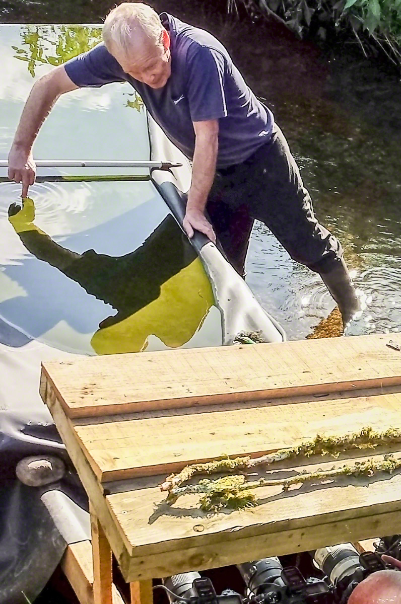
The Tricky Task of Focussing..
Our guide, Mick, was really helpful in making sure that we got everything right, and all came away with some excellent shots. Here Mick is holding a bar across the centre of the pool and using a handy finger knuckle placed mid tank for us to focus on (you can just see a head at a camera in the lower right hand corner). This is crucial because we were all using 70-200mm lenses at 200mm on full frame bodies. As you can see from the pictures, the Kingfishers were about 1.5m away, and this would mean a depth of field of about 2cm at f8 so there is no room for error and a certain amount of luck is still required.
F8 is about all you can afford in the dance between exposure value and ISO. To guarantee sharp shots you need a shutter speed of about 1/2500 of a second. We set auto ISO and aperture priority (i.e. to keep the camera set at f8) and a minimum shutter speed of 1/2500 s in the auto-ISO settings. We had great light and, with a 1 stop negative exposure compensation set to avoid blown highlights, the ISO ranged between a minimum of 720 and a maximum of 11,400 during the day. This said my keepers were evenly spread between ISO 800 and 7,200. No problem at all for the D4. You still need to take lots of shots however, because only some of them will be critically sharp and in frame. This depends partly on your timing, but mostly on where the Kingfisher dives and where he comes out again.
Participants were mostly shooting Nikon (1 D4s, 2x D4s and a Canon 5d MkIII). We were all using the Hahnel Giga T Pro II Wireless Timer Remote (by complete coincidence) and were able to set separate channels in order not to fire each other’s cameras. We were also able to help each other out because 3 of us hadn’t got much experience with the remote trigger, presumably purchasing them for this workshop! They worked flawlessly throughout the day though so they can be recommended as a reliable radio trigger.
Two Camera Setup
Having a perch, as well as a diving tank, gave the opportunity to shoot two cameras simultaneously (slightly tricky the first few times). This is made easier by the remote control, but you do have to watch that the handset doesn’t time out because it defaults to single shot when you first turn it on. This can be deceptive because you do get 3 shots if you hold the button down and, with other cameras firing at the same time, it’s easy to think that you are shooting continuously when you are not. So this is me in the hide with my D810 feeling very lucky indeed (though looking like I’ve just seen an alien)!

Selfie..
Not the best picture of myself I’ve ever taken, but I suppose given the conditions, my old Galaxy S4 did a decent enough job with it’s microscopic sensor, lens and 8 bit jpeg files. I’d probably just realised that my shutter speed was too high!
For the perch shots, given the very short distance to the perch, from the hide, it suited me to use my 300mm f2.8 with 2x teleconverter rather than my usual 600mm f4. I have been caught out once or twice recently by the 5m minimum focus distance on the 600. The 300mm Nikkor can focus down to 2.2m, which was crucial here. I must say that even with the 2x teleconverter the results are still very sharp, but you do lose 1 stop of light (f5.6) compared to f4 with the 600. This isn’t really a problem provided you keep your brain engaged!
One of the worries, with a shoot like this, is that you will miss a crucial setting on the camera. Prior to arriving at the hotel the night before, I had set both camera bodies up for the diving shots (i.e. auto-ISO and a minimum shutter speed of 1/2,500). You don’t need that kind of speed on the perch shots, unless you want to capture an in-flight arrival or departure from the perch. It’s not that there is really a problem with auto-ISO per se, but you do need to remember to tone down the minimum shutter speed, or better still (for me anyway) move to aperture priority with a fixed ISO. I prefer to use VR on the D810 with a shutter speed close to 1/500th second for the Perch Shots. This is plenty stopping power for subject movement and camera shake, providing me the sharpest results on the high-res sensor. On the D4 my VR threshold on the 600mm is 1/160th second (I prefer 1/250th second if I’m shooting with the 1.4 teleconverter) but this doesn’t give a tack sharp result on the D810 so I like to go higher. Obviously above 1/500th second you can introduce shake with the VR so you need a shutter speed to match the reciprocal focal length (1/600th s or above in this case).
The End Result
The setup above may appear Heath-Robinson, but it is just perfect for the task. Take a look!
Until next time..
Cheers,
R.
Feb
22
Kingfisher Diving Supplement
How do Kingfishers Dive for Fish?
This Kingfisher diving supplement adds to my post from yesterday A Few Days Out. I’ve examined my images from the Dumfries and Galloway shoot very carefully and I have realized something else important that I wish to share.
To recap:
- The Kingfisher eyes up the fish from the side of the tank
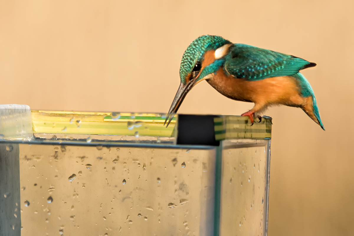
Eyeing up the Prey..
- The Kingfisher points his beak at the fish he wants several times
- Then there is an extra long stretch, and you see the bird go into the water
New Insights..
Having looked at my images very carefully, here is what happens next:
- The Kingfisher gives the extra long neck stretch then
- Flies upwards and backwards along the line of his beak keeping the fish in sight
- Then after gaining sufficient height, dives down and forwards again into the water to catch the fish
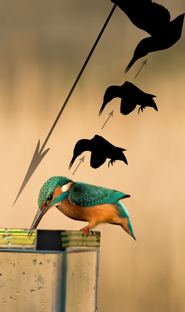
Flight Path for a Dive..
- This allows you to aim your camera along the flight-path much more accurately because you don’t have to overlap both sides of the tank just in case.
Some Action..
This is a little better than the Gif I published yesterday as it does show part of the backward flight prior to the dive. The shot 3 seconds before this sequence (not shown) has the Kingfisher looking at the fish, but before committing to dive. Fascinating stuff!!
Kingfisher Diving Sequence..
Until next time,
R.
Recent Comments